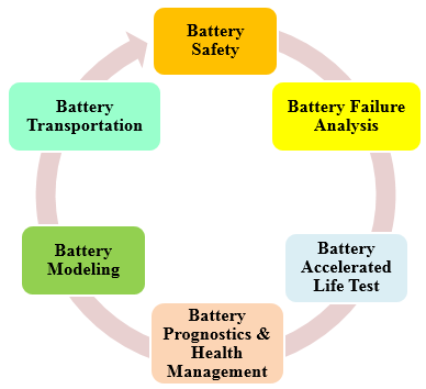
CALCE Battery Team is conducting applied and fundamental research to enable the reliable and safe development and operation of battery components and systems in real world applications. Studies include research on fundamental processes that degrade battery cells or lead to catastrophic explosion events, accelerated battery testing and qualification methods, battery failure analysis tools, pack integration and balancing strategies, novel sensing technologies, battery management system design, and advanced data science techniques for implementation of battery prognostics and health management (PHM) solutions. While our main focus is the state-of-the-art lithium-ion batteries, we have also undertaken projects pertaining to other chemistries including alkaline cells, primary lithium batteries, and lead-acid batteries.
CALCE battery team is headed by Prof. Michael Pecht and consists of senior research scientists, PhD students, and visiting scholars. In our over 20 year history, we have been generously supported by various government organizations and industry giants from consumer electronics, aerospace, medical, and automotive sectors. The Battery team uses state-of-the-art equipment for cell-to-pack level cycle testing, cell construction and disassembly, abusive (overheating, overcharge, short-circuit) testing, and material characterization. We place strong emphasis on the practicality of our research and the collaboration between industry and academia. Our current projects spread across areas associated with the entire life cycle of Li-ion batteries and span from multi-year battery academic research to month-long consultancy/testing projects.
Exploration of Novel Accelerated Testing Conditions for Qualifying Li-ion Batteries
Life testing of Li-ion batteries is conducted for qualification purpose by assessing its capacity fade based on the requirements for its targeted application. However, testing at normal operating conditions can be quite time-consuming. To identify highly accelerated testing methods, CALCE has been collaborating with two major consumer electronics manufacturers and 6 of the world’s largest battery manufacturers. While the effects of temperature on accelerated degradation of Li-ion battery performance have been studied and modeled in the literature, the combined effects of discharge C-rate with other factors still require deeper understanding.
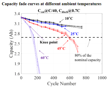
Increasing the charge/discharge C-rate reduces the time required to conduct a charge-discharge cycle and affects capacity fade over cycles. Of note is whether discharge C-rate affects battery capacity fade behavior, through ohmic heating and the resulting increase in battery temperature or whether the C-rate has its own unique degradation effects. Other factors of interest include the effects of rest time after batteries are fully charged on capacity fade and on degradation acceleration. Depth of discharge and charge cut-off current are additional related factors which can determine the state of charge ranges during cycling and can be used for accelerating the battery degradation.
References: Accelerated Cycle Life Testing and Capacity Degradation Modeling of LiCoO2-graphite Cells , Weiping Diao, Saurabh Saxena, and Michael Pecht, Journal of Power Sources, Vol. 435, September 2019, DOI: 10.1016/j.jpowsour.2019.226830.
Accelerated Degradation Model for C-rate Loading of Lithium-ion Batteries, Saurabh Saxena, Yinjiao Xing, Daeil Kwon, and Michael Pecht, International Journal of Electrical Power & Energy Systems, Vol. 107, pp. 438-445, May 2019, DOI:10.1016/J.IJEPES.2018.12.016.
 Thermal Runaway Characterization of Li-ion Batteries
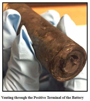
Recent Li-ion battery fire incidents in smartphones, hover boards, e-cigarettes, electric vehicles, and aircrafts highlight the limited understanding of battery thermal runaway failure mechanisms. Various studies have been conducted to investigate Li-ion thermal runaway failures but still the literature is inadequate for designing a safety system. CALCE is currently studying the effects of thermal and mechanical design parameters (e.g., venting) and operating conditions on Li-ion battery thermal runaway by performing a detailed electrical and thermal characterization of battery under catastrophic failure conditions to improve the safety mechanisms and thermal management of these batteries.
Commercial 18650 Li-ion cells are used for the experiments which have a charge cut-off voltage of 4.2 V and a discharge cut-off voltage of 2.5 V, specified by the manufacturer. The batteries are taken to specified SOC levels by charging and discharging the cell using an Arbin BT2000 Battery Tester. In order to understand battery thermal runaway behavior, heating wire is wrapped around the cell and supplied by DC power and Thermo couples are mounted near the two terminals of the cell to monitor the cell surface temperature. The cell voltage measurements are recorded during the entire testing.
 Investigation of Tab Design and Failures in Cylindrical Li-ion Batteries
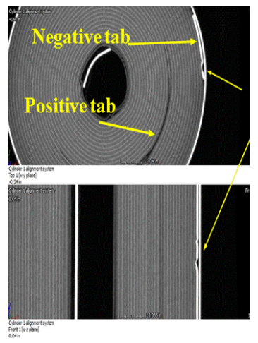
Lithium-ion (Li-ion) batteries have powered today’s portable and rechargeable products, and the cylindrical format is widely used in applications ranging from e-cigarettes to electric vehicles. The tabs in these batteries connect the electrodes (current collectors) to the external circuits. Li-ion battery failures such as fires and explosions can be caused by manufacture defects, especially associated with tab defects such as welding burrs and improper tab locations. The electrode tabs are the metallic strips that are welded onto the current collectors without active materials. When the battery is charged or discharged, the temperature around the electrode tabs is higher than other places inside the cell due to the high current density. CALCE is studying the effect of tab design and placement on battery reliability and safety.
Partial State of Charge (SOC) Cycling Effects on Capacity Fade of Lithium-ion Cells
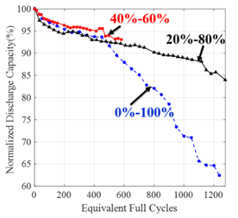 In practical applications, batteries may undergo charge-discharge cycling only for partial SOC ranges as opposed to the full 0%–100% range. CALCE has been performing cycle life testing of commonly used graphite/LiCoO2 pouch cells in different SOC ranges (e.g., 0-100%, 20-80%, 20-100%) to understand the effects of different SOC ranges on battery capacity fade and to model the battery capacity fade as a function of mean SOC, ∆SOC and cycle count. The developed models can be used for battery health management in field applications as well as for accelerated testing during battery qualification.
SOC ranges during cycling affect degradation mechanisms such as SEI layer formation and crack generation in the electrode. For example, as we increase the upper limit of SOC (end of charge voltage) in cycling, the amount of lithium in the anode increases, resulting in anode lattice volume expansion and causing localized stress. Also continuous cycling with higher ∆SOC value increases the probability of crack generation in the anode due to cyclic fatigue. These cracks in the anode provide fresh sites for electrolyte reduction and SEI layer growth, causing loss of cycleable lithium and higher electronic resistance. The figure below shows the effect of lowering the ∆SOC on the battery degradation.
Reference: Cycle life testing and modeling of graphite/LiCoO2 cells under different state of charge ranges, Saurabh Saxena, Christopher Hendricks, and Michael Pecht, Journal of Power Sources, Vol. 327, pp. 394-400, September 2016.
Management of Imbalances in Parallel-connected Lithium-ion Battery Packs
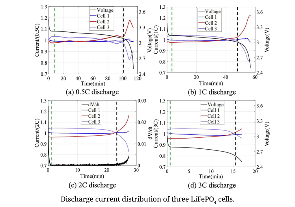
Uneven electrical current distribution in a parallel-connected lithium-ion battery pack can result in different degradation rates and overcurrent issues in the cells. Understanding the electrical current dynamics can enhance configuration design and battery management of parallel connections. This study presents an experimental investigation of the current distribution for various discharge C-rates of both parallel-connected LiFePO4 and Li(NiCoAl)O2 cells. A first-order Thevenin model for current distribution calculation was applied to assess the maximum discharge current discrepancy between cells when the number of cells increases. This study reveals why balancing circuits are seldom implemented on cells in a parallel connection, and provides guidance on reducing cell imbalances by managing battery operation in terms of state of charge range and discharge C-rates, as well as improving connection design.
Reference: Management of imbalances in parallel-connected lithium-ion battery packs, Diao, W., Pecht, M., & Liu, T., Journal of Energy Storage, Vol. 24, 2019, 100781.
Physics-based Electrochemical Model for Lithium-ion Battery State-of-charge Estimation
As electrochemical models can accurately simulate battery behaviors with the entire scope of state of charge (SOC), they are very appealing in BMS. However, the large computational cost of solving partial differential equations limits their practical applications. On account of low computational cost, simplified electrochemical models are more suitable. A simplified electrochemical thermal coupling model with reduced and regrouped model parameters was established and a method for nondestructive parameter estimation for individual cells was developed based on excitation response analysis. The parameters were classified into two categories: inherent characteristic parameters and mechanistic parameters. Inherent characteristic parameters could be obtained by consulting manufacturers directly or measuring. Mechanistic parameters were obtained by the excitation response analysis. According to different response time of different processes in the developed model when a cell was applied with different current excitations, the corresponding parameters were then obtained by least square fit.
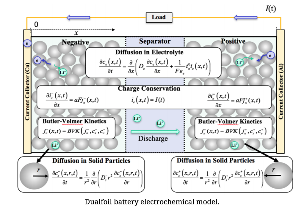
State-of-charge (SOC) is one of the most critical parameters in battery management systems (BMSs). SOC is defined as the percentage of the remaining charge inside a battery to the full charge, and thus ranges from 0% to 100%. This percentage value provides important information to manufacturers about the performance of the battery and can help end-users identify when the battery must be recharged. Inaccurate estimation of the battery SOC may cause over-charge or over-discharge events with significant implications for system safety and reliability. Therefore, it is crucial to develop methods for improving the estimation accuracy of battery SOC. An electrochemical model for lithium-ion battery SOC estimation involves the battery’s internal physical and chemical properties such as lithium concentrations.
To solve the computationally complex solid-phase diffusion partial differential equations (PDEs) in the model, CALCE developed an efficient method based on projection with optimized basis functions and a novel moving-window filtering (MWF) algorithm to improve the convergence rate of the state filters.
Reference: A Physics-Based Electrochemical Model for Lithium-Ion Battery State-of-Charge Estimation Solved by an Optimised Projection-Based Method and Moving-Window Filtering , Wei He, Michael Pecht, David Flynn, and Fateme Dinmohammadi, Energies, Vol. 11, No. 2120, pp. 1-23, 2018, DOI: 10.3390/en11082120.
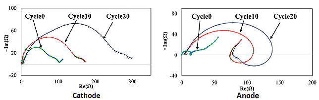
Electrochemical Characterization of Lithium-ion Batteries Using a Three-electrode System
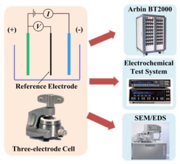 Recently, Lithium-ion batteries have been used in many electronic devices including laptops, smartphones, electric vehicles (EVs) and are also being considered for military and space applications. Generally, (commercial) Li-ion batteries have two-electrode. Therefore, the battery voltage or impedance can be measured only across the negative and positive electrode. In order to understand the fundamental electrochemical characteristics and to utilize the Li-ion battery chemistry more efficiently and safely, it is of interest to study the performance of each electrode separately. A three-electrode system is able to interpret the electrochemical characteristics of the individual electrodes. A widely used commercial 18650 battery (LiFePO4/ graphite) was reconstructed into a three-electrode full cell. Based on the three-electrode cell, the voltage and impedance of not only the full cell but also the individual electrodes were monitored. Accordingly, the electrochemical behavior of the commercial cell was explained and the contribution of each electrode to the full cell was identified.
Dendrite Formation Mechanism
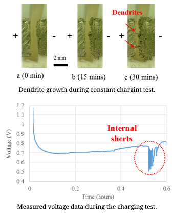
Lithium-ion batteries are commonly used in daily life. Concerns regarding lithium-ion battery safety are increasing with the widespread use of these cells in various applications. Among all the reported battery incidents, lithium dendrite formation causing internal short circuits was considered as the direct or indirect reason for battery failure. Dendrites can cause short-circuits, which can lead to catastrophic failures and even fires. Lithium dendrite is a metallic microstructure that forms on the negative electrode during the charging process. This is one possible reason for the internal short-circuits of lithium ion batteries. The lithium dendrite issue can occur in the lithium ion batteries when the battery is overcharged or charged at low temperatures. The dendrite growth is influenced by the applied current density.
In order to increase Li-ion battery safety, it is necessary to conduct research on lithium dendrite formation mechanism. For this purpose, an in-situ observation method was used to detect dendrite formation at various current densities and temperatures. The relationship between the applied current density and the dendrite growth rate is the research focus in the first step of study. In order to determine the dendrite growth rate, a symmetrical lithium cell (both the positive and negative electrodes were made of lithium metal) was charged at constant current. The developed in-situ testing method can be used for identification of dendrite formation inside cells. Battery safety operation boundary conditions can be determined using this work.
Reference: In-situ Observations of Lithium Dendrite Growth, Lingxi Kong, Yinjiao Xing, and Michael Pecht, IEEE Access, Vol. PP, Issue 99, February 21, 2018, DOI: 10.1109/ACCESS.2018.2805281.
Ultrasonic Health Monitoring of Lithium-ion Batteries
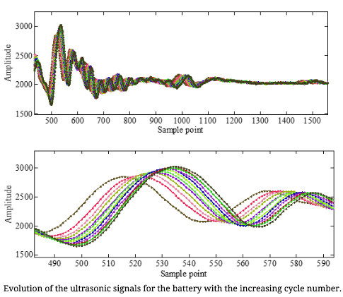
Early detection of the potential degradation in the Lithium-ion batteries can avoid catastrophic failure and reduce the maintenance cost. In the conventional battery failure detection system, the sensors can only detect the external signals of the cell, such as the current, voltage and temperature. However, the cell’s health state cannot be directly reflected from these signals. Actually, the health state of a cell is also physically coupled with the distribution and changes in the material properties, such as the density and modulus. Thus, a sensor that can sense the inherent physical changes in the cell during operation is more desirable for early detection of the degradation in the cell. Ultrasonic inspection method is used to detect internal material defects in metallic, composite materials, etc. This method has the potential to reflect the internal state of the cells, and provide early fault indications of failures, such as of internal gas formation, material deposition, and internal density changes.
We are now conducting ultrasonic test for three-type of polymer lithium-ion batteries using a set of ultrasonic hardware provided by X-wave Innovations, Inc. This hardware contains of a thin transducer which is mounted on the cell surface using petroleum jelly, a pulser-receiver (model US-Key) with DAQ capability. This hardware has small volume and low power compared with commercial bulky ultrasonic probes and equipment. Ultrasonic signals are collected after every charge-discharge cycling test of the cells. The time of flight and amplitude of the reflected echo are extracted from the ultrasonic signals. Now it can be seen that there is a strong correlation between the signal features and the cell capacity. This results preliminary verify that the ultrasonic signals can provide very useful information to indicate the health state of the cell and the ultrasonic inspection method can be used for early degradation detection of the cell.
Reference: Ultrasonic Health Monitoring of Lithium-Ion Batteries , Yi Wu, Youren Wang, Winco K.C. Yung, and Michael Pecht, Electronics, Vol. 8, No. 751, DOI: 10.3390/electronics8070751.
Battery Management System (BMS) Research
CALCE is dedicated to developing a BMS that not only assures safe usage, but also provides the most reliable performance and operational battery health information.
A BMS is an electronic device that manages a rechargeable battery in order to protect it from damage, prolong its life, maintain it in a healthy state, and provide the user with its operational status. A BMS consists of a number of sensors that measure the battery parameters (current, voltage, impedance, and temperature). The central unit of a BMS is comprised of a set of models and algorithms that estimate the battery SOC and SOH and then, based on the state estimation, make control strategies.
Another essential function of a BMS is cell balancing, which is vital for maximizing the usable battery capacity and lifetime. A typical BMS for electric vehicles (EVs) should contain the following functions: data acquisition, cell protection, charge/discharge control, SOC and SOH estimation, cell balancing, thermal management, and communication. The problem of state estimation must be considered in the context of the entire BMS. Certain applications may have restrictions on the types of data that can be collected. For example, a BMS in an EV can rely on frequent discharge data in order to make SOC estimations, whereas a BMS in a standby power supply must make state estimations offline due to infrequent use.
Therefore, the type of sensors available to a BMS must be considered when developing a state estimation algorithm. In order for these algorithms to be used effectively, they must interact with other subsystems of the BMS. If SOH monitoring is applied to individual cells in a multi-cell battery pack, then SOH can be used to determine when to perform cell balancing. If a voltage measurement largely disagrees with the modeled voltage in the SOC algorithm, then a fault condition could be triggered and the BMS should stop current flow through the battery. A high-level schematic that outlines some of the interactions between subsystems of a BMS is shown below.
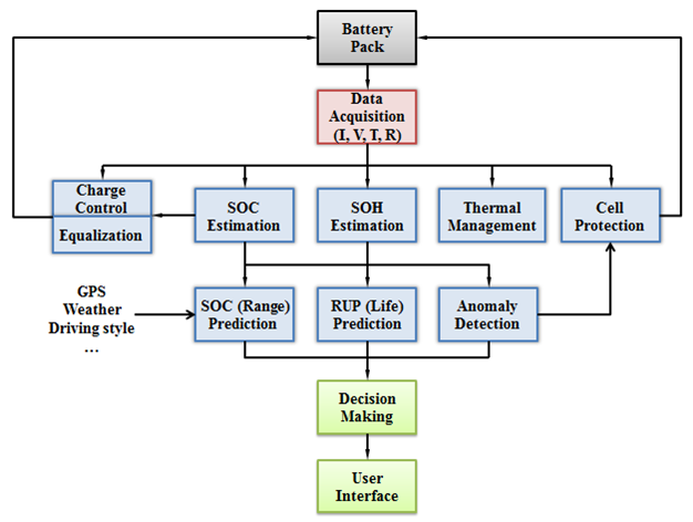
A high level Schematic of a BMS
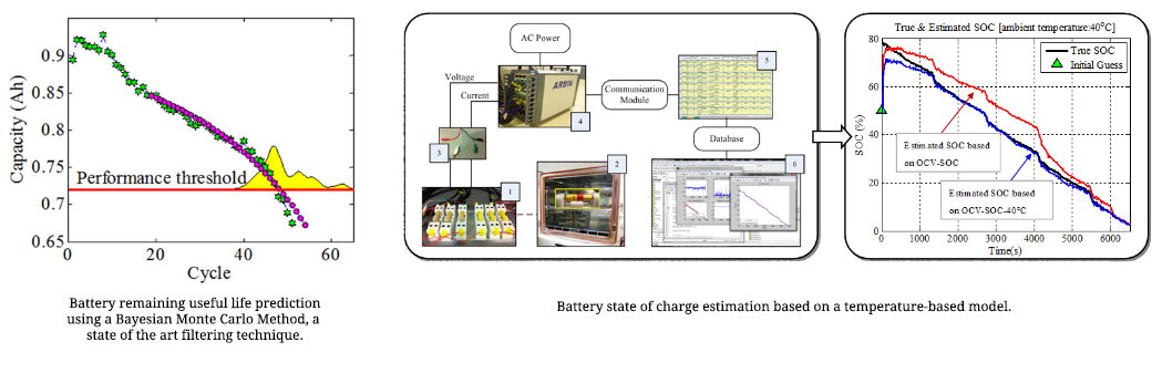
Real-time data processing algorithms are key components in BMSs. These algorithms evaluate inputs such as current, voltage, and temperature in order to estimate the remaining charge in a battery (the SOC), the amount of degradation that has occurred in a battery (the SOH), and the remaining time the battery can operate before it must be replaced (the remaining useful performance, or RUP). SOC is necessary to ensure that a battery can perform a given task before it requires a recharge while SOH and RUP are used for planning maintenance and battery replacement. As shown below, A state of the art filtering technique that CALCE has developed is being applied to estimate and predict battery SOH and RUP and A temperature-based model is being used to estimate battery SOC taking into account different ambient temperatures.
The CALCE Battery Research Group features state-of-the-art shared instrumentation facilities that support high-level scientific research and student training. Each Facility offers multiple research instruments and high-end tools, needed to support the diverse research activities within the Department. These facilities welcome users from the many universities, companies and federal laboratories, providing hubs for collaboration and innovation.
Electrical Characterization
Cadex C8000 Battery Test System
3 channel, 1.2V - 36V, 10A charge and discharge per channel,100W per channel on charge; 80W on discharge
Agilent 34970A Data Acquisition
2-slot mainframe, 96 matrix crosspoints, Measures and converts 11 different input signals, 60 channels input
Princeton Applied Research's VersaSTAT 3
Potentiostat/galvanostat with frequency response analyzer (FRA) 1 µHz to 1 MHz, Max Current: ±2A.
Neware BTS4000
3 channels, current control range of 0A to 3000A, voltage ranges of 0V to 110V, Accuracy of ∓0.05% FS
Arbin BT2000 Battery Test System
15 channel battery tester, tests up to 5V per channel, 0.02 to 0.1% FSR control
Arbin BT-I
15 channel battery tester, 1mA-10A, 10-20V per channel, 0.02 to 0.1% FSR control
Olympus EPOCH XT Ultrasonic Pulser and Receiver
Pulse repetition frequency (PRF): 9 Hz to 1 kHz 5 megahertz, ¼” diameter ultrasonic transducer
Environmental Chambers
MBRAUN Glove Box Workstation
A Stainless steel design with Inert gas purification system having Large antechamber with sliding tray and PLC-M
Yamato DVS 402
Laboratory Constant Temperature Ovens with temperature ranging from Room temp +4°C to 260°C with accuracy of ∓1.0°C
Thermo Temperature Humidity Chamber
Incubator- Temperature range: Ambient +4° to 75°C. 120V/300W, True laminar airflow for tight temperature uniformity
Mechanical Testing
A range of equipment is available to measure electrical, thermal, mechanical, and material properties critical to the performance and reliability of systems. Specific equipment includes:
TA's Dynamic Mechanical Analyzer
Texas Instrument's Rheometrics Solids Analyzer,generates 0.0001N-18N Force with force resolution of 0.00001N, Deformation range: ∓0.5 to 10,000 pm, Temperature Range:-150 to 600°C
Data Physics 1D Electrodynamic Shaker
Max Sinusoidal Force- :468Kgf, Max Random Force:261Kgf, Max Shock Force:994Kgf, Frequency Range: 5- 3000Hz
Perkin-Elmer Differential Scanning Calorimeter
Furnace: 19 to 600°C; Maximum scan rate: 500°C/min; Sensitivity:0.1µW, Uses Nitrogen as shield gas and Helium as purge gas
Vibrotron 6D-Electrodynamic Shaker
Peak force of 4200N for sinusoidal vibrations, 3400N RMS force for random vibrations and 7100N force for classic shock, Frequency range:5- 4500Hz
DAC Torsion Tester
ElectroMechanical Test Machine with Torque range of 1Nm to 5.5kNm with frequency range of 2Hz- 30Hz capable of performing static, dynamic and fatigue testing applications
Mechanical Test System
Axial and torsional actuators; Temperature Range: -129° to 540°C, Digital controllers with high channel density, high capacity and superior configurability
Failure Analysis
Extensive experience and state-of-the-art equipment are used for failure analysis of batteries, electronic components, printed circuit boards, connectors, products and systems.
Zeiss AxioCam MRc5 Optical Microscopy
4 Megapixel (2584 x1936) resolution, 12 bit / 12 Mhz pixel clock, 36-bit color depth, Dynamic range of 1:1300 for optimal
Agilent Fourier Transform Infrared Spectroscopy
Multi-range FT-IR spectrometer capable of both rapid scan and step scan operation. Spectral range 10,000-400/cm.
Nikon Atomic Force Microscopy
2D topography measurement, vertical resolution typically 50 pm, characterization of the topography and electrical, chemical, magnetic and mechanical properties
Fischer X-ray Fluorescence Microscopy
Micro-focus tube, measurement chamber with a C-slot, 4-x aperture changer, 3 primary filters, Larger measuring distances possible (DCM, stroke 0-80 mm)
GE Phoenix Nanome X-ray Microscope
Combined 2D / 3D CT operation, Digital image chain and active temperature-stabilized digital detector with 30 fps, 180 kV / 15 W nanofocus tube, 200nm detail detectability
Scanning Electron Microscopy/ Energy Dispersive Spectroscopy
2 modes: High vacuum, Low vacuum and ESEM, Resolution range: 0.8nm- 3nm, Accelerating voltage: 200V – 30kV, Digital video recording, Vacuum: 6e- 4000Pa
OKOS Scanning Acoustic Microscope
Digital Pulse Receiver, Optional second channel, Max velocity: 1499mm/s, Accuracy and repeatability: ∓0.5 micron
Thermo-mechanical Analyzer
Temperature Range: -151 to 1,000 °C, Precision: ∓1°C, Maximum Sample Size: 26mm x 1.0mm x 4.7mm, Measurement Precision: ∓0.1%
Facilities
CALCE Center for Advanced Life Cycle Engineering 1103 Engineering Lab Building
University of Maryland
College Park, MD 20742
Phone: 301-405-5323 | Fax: 301-314-9269
For more information, contact Prof. Michael Pecht (301-405-5323) or Dr. Michael Osterman (301-405-8023).
Planning a Visit?
The closest available lots to CALCE are:
Here are helpful links to parking accomodations.
You may wish to use the interactive UMD Map to plan your visit.