Halogens are the elements in group VII including fluorine, chlorine, bromine, iodine, and astatine. They can be used in flame retardants for electronic products to meet flammability standards. The advantages of halogenated flame retardants is due to the high flame retardance, ease of blending, good compatibility with electronic materials, good electrical insulation, and cost. However, most compounds that contain bromine and chlorine are endocrine disruptor, and tends to be likely to be persistent, bio-accumulate, and be toxic. Moreover, when the electronic products are burned, halogens can be extremely toxic to the environment, animals and people. Since the beginning of 1990s, the electronics industry has faced pressure from a multitude of sources to produce more “green” or environmentally friendly products. These pressure sources include health and environment concerns, recycle and recovery problems, global laws and regulations, customer inclination, and non-governmental organizations (NGOs) pressure. Many kinds of halogen-free flame retardants have been proposed in recent years, each of them exist advantages and disadvantages comparing to the halogenated flame retardants. Unfortunately, the replacement by halogen-free materials has been found to result in degraded electrical and mechanical performance, as well as decreased reliability. As a result, halogen-free is not a drop-in replacement, and companies providing products and systems must understand their limitations. Finally, additional concerns with manufacturing and supply chain perspectives should also be considered during halogen-free transition.
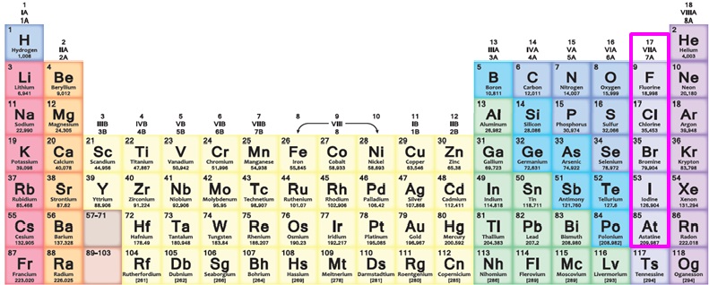
Halogens are the elements in group VII including fluorine (F), chlorine (Cl), bromine (Br), iodine (I), and astatine (At), as marked in the following figure. The name halogen was from the Greek roots hal- (“salt”) and -gen (“to produce”). They all produce sodium salts in similar properties. Halogens easily dissociate into ions and combine with surrounding elements to form compounds due to their high levels of electronegativity. Bromine and chlorine compounds are widely used as flame retardants in electronic industry because of the following advantages: high flame retardance, ease of blending, good compatibility with electronic materials, good electrical insulation, and cost.
Halogens in the Periodic Table of the Elements [1]
Electronic products can manipulate electrical current and convert it into heat, light, or motion to accomplish some meaningful action. For example, audio electronic devices manipulate the electric current by adding sound information so that people can listen to music or talk on a cellphone. Electronic products consist of many materials, including ceramics, glass, alloys, and polymers. Because of the flammability of polymers, flame retardants are added into polymers, such as encapsulants and laminates, for fire safety concern. The purpose is to retard or extinguish fires due to unanticipated situations. For example, short-circuits can lead to high currents and generate high temperature conditions.
Green engineering requires environmental consideration at the design phase of a product. This consideration includes all material and energy requirements and their effects over the lifetime of the product. Material requirements include those for both products and processes. The focus on energy must include the energy to make, use, and dispose of the product. Green design and manufacture leads to the understanding of the interplay among processes and flows and the optimization of the various considerations that are present. Green electronics is the application of environmentally considerate design and manufacture to electronic products. Environmentally considerate electronic products include those made with recycled and recyclable materials and energy efficient processes. Green electronic products do not become part of the solid waste stream, and their processes do not contribute liquid and gaseous emissions to the environment.
Manufacturers add flame-retardant (FR) chemicals to their materials during or after manufacture to inhibit or suppress combustion. FRs interfere with combustion at various stages of the process, such as during heating, decomposition, ignition, or flame spread. One goal is to prevent the spread of fires or delay the time of flashover. Studies show that the use of FRs in the manufacture of electronic equipment, upholstered furniture, construction materials, and textiles save lives from fire [2].
There are various kinds of FRs, such as halogenated, chlorinated, phosphorous-based, nitrogen-based, and inorganic. Different types of FRs are better suited for different applications. Their suitability depends on compatibility with the material to be flame-retarded, the fire safety standards with which the product must comply, reliability, and cost considerations.
The halogens are the chemical elements fluorine, chlorine, bromine, iodine, and astatine. Manufacturers do not use fluorine and iodine-based FRs in practice because neither type sufficiently interferes with the combustion process: fluorine has too strong a bond and iodine too loose a bond to carbon. In plastics, brominated flame-retardants (BFRs) have been the most effective flame retardant when both performance and cost are considered.
Bromine in its elemental form is a highly volatile reddishbrown liquid at room temperature. However, bromine never occurs in its elemental form naturally, but in compounds with other substances, known as bromides. The recoverable form of bromine is from soluble salts found in seawater, salt lakes, inland seas, and brine wells. It is these bromides, which become the raw materials to produce commercial brominated products. Bromine production exceeds 470,000 tons annually [2].
Halogenated FRs primarily consist of chlorine and bromine. Through BFRs’ unique chemical interaction with the combustion process, bromine is more effective than most of the alternatives, meaning that a much lower quantity of flame retardant achieves the highest fire resistance. As a result, BFRs have been used to protect a wide variety of products, including electrical and electronic components and products, such as televisions, computers, radios and stereo systems. BFRs (39 percent) and chlorinated flame retardants accounted for 45 percent of the flame retardant worldwide market in 1998 [2]. Electrical and electronic components accounted for 56 percent of the BFR market.
There aredifferent types of BFRs [3], such as PBBs (polybrominated biphenyls), PBDEs (polybrominated diphenyl ethers), TBBPA (tetrabromobisphenol – A), and HBCD (hexabromocyclododecane). Each of these BFRs has very different properties. Interestingly, the Association for Connecting Electronics Industries (IPC) “recognizes the term halogen-free as a marketing term only and does not support it as an industry standard for materials and final products containing any level of halogenated flame retardants” [4].
However, most compounds that contain bromine and chlorine are endocrine disruptor, and tends to be likely to be persistent, bio-accumulate, and be toxic. Uncontrolled recycle can cause these halogenated compounds to leak into the environment and involved in the food chain. Moreover, uncontrolled burning of halogenated electronic products can release toxic and corrosive gases to treat the environment, animals and people. Since the 1990s, the electronics industry has faced pressure from a multitude of sources to produce more environmentally friendly or green products. These pressure sources include health and environment concerns, recycle and recovery problems, global laws and regulations, customer inclination, and non-governmental organizations (NGOs) pressure. The RoHS (restriction of the use of hazardous substances) regulation of by the European Union (EU) has been turned into effective from 2006, substances including lead, mercury, cadmium, hexavalent chromium,, polybrominated biphenyls (PBBs), and polybrominated diphenyl ethers (PBDEs) are restricted. PBBs and PBDEs are groups of brominated compounds, and are common flame retardants in electronic industry. Restrictions on these flame retardants has forced the manufacturers and suppliers of the electronic components and the printed circuit boards (PCBs) to find and develop alternative halogen-free materials. Recently, the driving force for halogen-free electronics comes from the consumer electronics companies who commits to offer more green products because of the environmental responsibility. The industry standard for halogen-free materials is defined as having less than 900 ppm of chlorine or bromine and less than 1500 ppm of total halogens (International Electrochemical Commission, Restriction Use of Halogen (IEC 61249-2-21)) [5]. The JPCA ES-01-1999 (Japan Printed Circuit Association) defines halogen-free as a maximum concentration of 900 ppm for bromine, chlorine, or antimony [6].
Many studies of halogen-free flame retardants have been developed in recent years. The results showed that halogen-free flame retardants exist both advantages and disadvantages comparing to the halogenated flame retardants. For example, iNEMI studies [7] compared the material properties of six commercially available halogen-free laminates with three brominated FR4 laminates as the baseline. The results showed the average out-of-plane coefficient of thermal expansion (CTE) of halogen-free laminates was 10% lower than the average of their halogenated counterparts. Generally speaking, lower out-of-plane CTE tends to exhibit longer plating through hole (PTH) reliability. However, the studies [7] also showed the halogen-free laminates absorbed 30% more moisture than their halogenated counterparts. Higher moisture absorption can induce adverse effects on the electronic products, such as popcorning and conductive anodic filament (CAF) formation. Moreover, halogen-free flame retardants have been found to exhibit degraded electrical and thermo-mechanical performance, as well as decreased reliability.
Flammability Requirements for Electrical and Electronic Products
There is a potential risk for electrical and electronic products to catch fire due to the short circuits, which can generate excessive current flow in the low resistance connection and cause extreme temperature conditions. Thus, the electrical and electronic products should own the ability to retard fire and comply with industry flammability standards for safety concern. Flame retardants are added into electronic products to reduce the risks of catching fire because they can stop or slow the spread of fire by increasing the threshold of fire ignition. Underwriters Laboratories (UL) 94 is a common standard to evaluate the flammability of plastic materials used in devices and appliances. UL 94 defines the flammability tests and assigns ratings based on the results. These results can serve as a preliminary indication for part manufacturers to select the right materials with corresponding flame retardance. The following table [8] lists the requirements for UL 94 V-0, V-1, and V-2 ratings. V-0 is stricter than V-1, and V-1 is stricter than V-2. In UL 94 test, the high V-0 rating means a piece of plastic material would exhibit slow flame spread and quick burning cease after removing the igniting flame. On the contrary, a specimen would ignite quickly and keep burning if the specimen could not achieve the V-0 rating.
|
Flammability rating UL 94
|
V-0
|
V-1
|
V-2
|
|
Burning time after flame application (s)
|
≤ 10
|
≤ 30
|
≤ 30
|
|
Total burning time (s) (10 flame applications)
|
≤ 50
|
≤ 250
|
≤ 250
|
|
Burning and afterglow time of specimens after second flame application (s)
|
≤ 30
|
≤ 60
|
≤ 60
|
|
Dripping of burning specimens (ignition of cotton batting)
|
No
|
No
|
Yes
|
|
Specimens completely burned
|
No
|
No
|
No
|
Health & Environment Concerns
BFRs, and particularly polybrominated biphenyls (PBB) and polybrominated diphenyl ethers (PBDE), contain one or more carbon rings, making them very stable. The chemical stability of these substances is a principal reason why BFRs have been the focus of international environmental debate [38]; they accumulate in the food chain and it is impossible to avoid dispersal into the environment by implementing treatment measures exclusively at point sources, such as waste water or air emissions [39,40]. The pollution thus occurs as both diffuse pollution and point-source pollution from the locations where the products are handled. Several studies also suggest possible dispersal of BFRs into the marine environment as well as into the air through evaporation [41,42,43].
Studies have measured rising levels of PBDEs in marine environments [44] and in human milk, adipose tissue, and blood [45], raising concerns because of PBDEs structural similarity to thyroid hormones [46]. Study reports of PBDE in sperm whale blubber suggest that the substances have permeated the food chain in the open sea far from the primary source [38]. Measurements in seals from the North Sea and Baltic Sea show that coastal fauna is also subject to considerable exposure to PBDE. PBDE has also been detected in fish from the Baltic Sea. Measurements of birds, seals and whales from the Arctic and the Faroe Islands also show that brominated flame retardants have dispersed far into the environment [47]. A Finnish study shows that the concentration increases with age, which is in accordance with the substances properties [48].
The majority of the brominated flame retardants have low acute toxicity. Nevertheless, in animal experiments, certain PBDEs have been shown to have harmful effects on liver, thyroid gland and fetuses in low concentrations. Certain PBDEs can also cause hormonal imbalance via the thyroid gland, and hence are suspected of disturbing development of the fetal nervous system [49–51]. Because of the similarities in the biochemical and toxicological effects of PBB, PBDE, and polychlorinated biphenyl (PCB), additive effects may occur.
DECA has been considered problematic because decabromodiphenyl has been found to enter into the human food chain [52]. While halogenated flame retardants, such as decaBDE, are being phased out across the market owing to their reported environment and health concerns, effective alternatives are being developed and replacing them by the end users. The following table is the health concerns with common halogenated compounds.
Health Concerns and Impacts for Common Halogenated Flame Retardants
|
Name
|
Health Concerns/ Impacts
|
|
Carcinogen
|
Mutagen
|
Reproduction
|
PBT1
|
vPvB2
|
|
PBBs
|
V
|
V
|
|
V
|
|
|
PBDEs
|
V
|
V
|
|
V
|
|
|
HBCD
|
|
V
|
V
|
V
|
|
|
TBBPA
|
V
|
V
|
|
|
|
|
CPs
|
V
|
|
|
V
|
V
|
|
TCPA
|
|
|
|
V
|
|
|
PCT
|
|
V
|
|
V
|
|
|
PCB
|
V
|
V
|
V
|
V
|
|
1: Persistent, bioaccumulative and toxic
2: Very persistent and very bioaccumulative
Global Halogen-free Legislation
Because the chemical properties of halogenated compounds can harm humans, animals, and the environment, many of them are subject to the European Union’s Restriction of Hazardous Substances (RoHS) directive. The directive’s purpose is to regulate and restrict electronics manufacturers from producing and using specific hazardous materials [53]. For example, polybrominated biphenyls (PBBs) and polybrominated biphenyl ethers (PBBEs) were banned by RoHS [54]. RoHS is heavily enforced throughout Europe, with manufacturers facing a multitude of penalties for noncompliance, including fines, impounded goods, and loss of manufacturers’ rights to sell products within the EU [55]. Additionally, companies outside of Europe are affected by RoHS, as suppliers to EU manufacturers and non-EU manufacturers who sell to the EU market must comply or risk facing penalty. For example, Palm, Inc., and Apple Computer, Inc., have both had to pull products from the EU market due to their products’ non-compliance with RoHS at various times [56]. The following table summarizes the limitation of halogenated materials in various countries.
Global Legislations for Halogenated Materials
|
Country
|
Legislation
|
Substances
|
Limitation
|
Effective date
|
|
EU
|
RoHS:2002/95/EC
|
PBBs/PBDEs
|
0.1%
|
July 2006
|
|
76/769/EEC; 89/677/EEC
|
PCB/PCT
|
0.005%
|
June 1986
|
|
76/769/EEC; 2002/45/EC
|
SCCPs
|
1%
|
January 2004
|
|
850/2004/EC; 2016/293/EU
|
HBCD
|
0.01%
|
March 2016
|
|
1907/2006/EC; 2017/227/EU
|
DecaBDE
|
0.1%
|
March 2019
|
|
USA
|
Various state laws
|
PBBs/PBDEs
|
0.1%
|
2006-2008
|
|
HBCD
|
0.1%
|
2017
|
|
DecaBDE
|
0.1%
|
2017
|
|
China
|
China RoHS
|
PBBs/PBDEs
|
0.1%
|
March 2007
|
|
Japan
|
Law for promotion of effective utilization of resources
|
PBBs/PBDEs
|
0.1%
|
July 2006
|
PBBs: Polybrominated Biphenyls; PBDEs: Polybrominated diphenyl ethers
PCB: Polychlorinated Biphenyls; PCT: Polychlorinated Terphenyls
SCCPs: Short Chain Chlorinated Paraffins
HBCD: Hexabromocyclododecane
Halogen-free Flame Retardants
The major applications of epoxy resins are for encapsulants, PCBs, composites, and adhesives [25]. The PCB laminates have to achieve a variety of mechanical and electrical requirements, and they also have to be flame-retardant. Brominated reactive compounds, such as TBBA, show sufficient flame retardance in glass fabric based laminates of the FR-4 class. However, these well-proven flame retardants were prohibited in July 2006 [26]. Therefore, manufacturers need to find alternative laminates with a halogen-free flame retardant system that meets the requirements.
Halogen-free flame retardants (HFFRs) have been rapidly developed since the 1970s [28,57-59] to meet the increasing needs of environmental protection. Until now, halogen-free flame-retarding CCLs (copper clad laminates) have been developed with high glass-transition temperature (Tg) [60],[61] and good mechanical properties [62]–[64]. Current halogen-free CCLs are primarily based on DOPO. Moreever, several DOPO modifications have been developed and are commercialized as either pure substance or phosphorus-modified epoxy resins.
Epoxy chemistry is still the preferred backbone for CCL applications. Halogen-free and phosphorus-containing epoxy resins have already occupied the halogen-free market . The number of DOPO modifications and phosphorus-modified resin suppliers has significantly increased and offers broad choices for CCL manufacturers. Other components, such as fillers (e.g., SiO2, alumina trihydrate, and talc) and new accelerators or curing agents, allow the development of halogen-free formulations to match various properties of improved electrical (low loss, high frequency) or mechanical properties (low coefficient of thermal expansion (CTE), higher thermal stability). These new materials make halogen-free alternatives more attractive to OEMs in new consumer products.
Epoxy resins with halogenated flame retardants can produce poisonous and corrosive gases and even super toxic dibenzodioxins and dibenzofurans [65],[66]. Therefore, application of halogen-free flame retardants is extensively investigated. A flame retardant should be carefully chosen not only for flame retardancy effectiveness but also for its effects on the overall properties of the polymer system. Two considerations should also be made when identifying possible halogen-free flame retardants: the mechanism of flame retardance and the ways of interaction in the polymer system.
The mechanism of flame retardance can be either physical or chemical. Possible physical interactions by a flame retardant include cooling the polymer below combustion temperatures, forming a char layer over the polymer to exclude oxygen in the system (intumescence), and diluting the amount of fuel in the system by the presence of an inert material. Chemical interaction includes mechanisms taking place in the gas phase, interfering and prohibiting the continuation of the combustion process, and mechanisms occurring in the solid phase, which can either break down the polymer or chemically form a carbon layer on the surface. In general, chemical interactions have been found to be most effective for flame retardance.
The other consideration is the additive or reactive interaction of the flame retardant with the polymer system. The interaction of the flame retardant with the resin material affects not only polymer properties but also processing and environmental issues. Reactive flame retardants are chemically built into the polymer structure and thereby provide a consistent structure for flame retardance and material properties. DOPO is an example of a phosphorus-based flame retardant. Additive flame retardants are incorporated by mechanical means and need to be uniformly dispersed in the system. In general, halogen-free flame retardants can generally be divided into three main chemical families.
According to the industry market research [67], alumina trihydrate (ATH) was the most popular flame retardants and accounted for almost one-third consumption of global market. ATH is expected to dominate the market through 2018. On the other hand, phosphorus-based flame retardants have exhibited the fastest market growth within all of the flame retardant products under the consideration of both cost and performance [68]. As a result, the market of phosphorus-based flame retardants overtook that of the brominated flame retardants and became the second place in the market in 2015. This fastest growth of phosphorus-based flame retardants will keep through 2020. Moreover, magnesium hydroxide (MDH) and melamine are also promising halogen-free flame retardants because of their above average market growth. However, the halogenated flame retardants with less hazardous effects will still share the market to some degree.
Despite the historic use of halogenated materials, the electronics industry in recent years has become increasingly aware of environmental concerns, and thus halogen-free materials have become increasingly popular. The use of halogen-free system flame retardants such as phosphorus system flame retardant has increased by past 20 years. However, ensuring the reliability of components that use halogen-free system flame retardants becomes a challenge for industries because the strength and heat resistance of these components may be inferior to that of conventional components.
Phosphorus-containing compounds are promising in halogen-free and flame-retardant applications of epoxy resins [69]–[71]. The radicals of H+ and OH– react with the PO– radical and HPO produced by the pyrolysis of phosphorus-containing flame retardant to reduce the energy of the flame in the gas phase. On the other hand, the PO– radical and HPO generally convert into polyphosphoric acid in the solid phase during decomposition. This reaction catalyzes the formation of a protective carbonaceous layer, which possesses high thermal stability and retards further decomposition of polymer chains.
There is a transition to manufacture halogen-free electronics today [72]. Laminates have been made this way because incineration of the PCBs generates dioxin potentially if it is not properly controlled. Bisphenol A is used as a precursor in traditional FR-4 epoxy manufacturing. Adding 10% of the brominated bisphenol A in the dicyandiamide (DICY) cured epoxy can form tetrabromobisphenol A (TBBPA). The function of the brominated bisphenol A is to provide protection of flammability. The same flame-retardant is also used in PN (phenol novolac)-cured epoxies. However, the brominated material is removed in halogen-free (HF) laminates [73], and is replaced by metal hydroxides, such as aluminum and magnesium hydroxides, which would release water vapor while heating [74]. Phosphorous-doped epoxy is also retardant to flame by charring the polymer during ignition [75].
Phosphorus-based Flame Retardants
Phosphorous compounds have been considered to be the primary alternative flame-retardant materials to replace halides in PCBs. However, halogen-free materials are not as efficient as halides. To meet the criterion of UL94 V-0, phosphorous compounds within PCBs are substantially increased, which makes the halogen-free PCB more brittle than a traditional PCB [30],[76].
The flame retardant mechanism operates primarily in the solid phase of a polymer, by removing water and creating a carbon-rich char on the surface of the polymer. This mechanism can usually generate very low smoke density and no release of corrosive, acid gases into the gas phase (like HCl or HBr for halogenated flame retardants). On a weight percentage basis, phosphorus is also more effective than bromine. For example, UL 94 V-0 can be achieved with 2.5 to 4 % phosphorus.
DOPO, OPS, APP, and PEPA (shown in the following figure [77]) serve as flame retardants in the epoxy resins. The purpose of using them is to study the influence of phosphorus on the flame-retardant efficiency of epoxy resins. DOPO has high thermal stability, good oxidation resistance, and good water resistance [78]–[81]; it is a popular phosphorus-containing flame-retardant that can react with the epoxy monomer. Using DOPO or its derivatives as a flame-retardant for epoxy resins has been reported [82]–[85]. Furthermore, the intumescent flame retardants (IFRs) have been considered as another promising material because of their low-toxicity, low-smoke, halogen-free, and high-efficiency properties [86]–[88]. For example, ammonium polyphosphate (APP) is a common IFR. Additionally, caged bicyclic phosphates have attracted attention among the organophosphorus flame retardants, and many studies have focused on them [89]. The caged bicyclic phosphates and their derivatives can serve as effective IFRs or charring agent in some polymers [89,90]. PEPA (1-oxo-4-hydroxymethyl-2,6,7-trioxa-l-phosphabicyclo [2.2.2] octane) is also a reactive phosphorus-containing FR with halogen-free flame retardant systems.
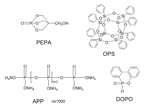
Typical chemical structures of flame retardants
Impact on Performance
The following material properties are considered critical to the performance and reliability of the PCBs, including moisture absorption, glass transition temperature (Tg), coefficient of thermal expansion (CTE), decomposition temperature (Td), and time to delamination (T-260 and T-288). Because the reinforcement glass does not easily absorb moisture, moisture diffusion will only occur through the epoxy. Epoxies also can absorb various moisture contents inherently. Moreover, different glass/resin ratios for the PCB constructions will result in various moisture concentrations and maximum moisture uptake values. In conclusion, the moisture absorption characteristics of PCB materials can vary according to the epoxy type, construction, and epoxy/fiber content [91].
Because halogen-free materials are different physically (filler) or chemically (matrix structure) from their halogenated counterparts, the performance and reliability between halogen-free and halogenated materials are also expected to be different. Many studies have shown the advantages and disadvantages of various halogen-free materials. Therefore, the encapsulant and PCB systems need to be adjusted or redesigned to meet technical requirements of expected applications [92]. For example, the peak temperature of lead-free reflow process is 30 to 40 °C higher than that of tin-lead process. The higher temperature might induce process issues caused by CTE mismatch and moisture. Moreover, for manufacturing consideration, the processability and moldability should also be taken into account for selecting the halogen-free materials.
The performance and reliability of PCBs can be largely affected by the absorption of moisture [93]. During the manufacturing process of PCBs, moisture could be absorbed by the epoxy/glass fiber prepregs from the wet processes or from the storage environment [94]. The locations containing moisture can be epoxy resins, resin/glass fiber interfaces, and the micro-cracks or voids within the PCB. The moisture can lead to prepreg/copper interfacial delamination, internal shorts by the metal migration (conductive anodic filament), and lower glass transition temperature [95]. Moreover, the moisture can expand tremendously at higher process temperature and cause popcorning defects in the encapsulants. Moisture can also impact the electrical properties of PCB on increasing its dielectric constant to reduce the switching speeds of electrical circuits and increase signal propagation time [96].
Mechanical Properties Performance
Halogen flame retardant (HFR)-free alternatives are not without issue when used in PCBs. HFR-free PCB laminates can negatively impact production, handling, and product performance. Studies have shown that the implementation of HFR laminates can lead to a decrease in electrical system performance, due to higher dielectric constants than are found in FR-4 materials that are currently widely used [34]. Higher dielectric constants can cause an increase in brittleness and a decrease in peel strength, due to a change in performance of the PCB epoxy materials [34]. Glass transition temperatures and moisture absorption may move in different directions, leading to unpredictable results [34]. Furthermore, as the amount of PCB layers increases, the performance issues listed above increase. However, despite some of the negatives associated with HFR-free PCBs, they outperform halogenated PCBs in many areas. For example, supplier datasheets show that HFR-free PCBs often have lower CTE, longer T-260 and T-288 times, and higher Td temperature [97].
Currently, most copper clad laminates are made from brominated flame retardants, which present environmental hazards, or phosphorus-containing resins. Phosphorus-containing resins have proven to be a satisfactory alternative to halogenated products, but they have a very high water absorption rate. As a result, their chemical resistance deteriorates. Therefore, there is a demand for products with less phosphorus. Other reports offer additional data regarding the reliability and performance of halogen-free PCB materials. A report by iNEMI [34] analyzed the technology readiness, supply capability, and reliability characteristics of halogen-free materials, and analyzed the feasibility of computer manufacturers converting to halogen-free materials. Another report by iNEMI [98] stated none of the tested halogen-free materials were equivalent to their FR-4 baseline. They observed generally higher Dk (effective dielectric constant) values and lower Df (effective loss tangent) values for halogen-free materials comparing to the baseline material. The property and performance differences of halogen-free material will depend on the design and demands of the products in which they are incorporated.
Additional studies have shown that halogen-free PCBs are prone to two specific defects: graping, and the head-in-pillow defect. Removal of halogens can result in graping, which is described as “an incomplete coalescence of the solder paste leaving a rough uneven surface” [97]. As the removal of halogens can result in a change in the CTE of the PCB, their removal can, in turn, lead to the head-in-pillow defect [97]. Graping and the head-in-pillow defect create a challenge for solder paste manufacturers to produce halogen-free solder pastes that perform as well as the current halogenated materials [97]. Furthermore, halogens are used in solder pastes and fluxes. The same study went on to show that the removal of halogens can negatively impact wetting and coalescence. Thus, the removal of halogens from these materials will directly impact the PCB assembly process [97]. Many studies show that halogen-free PCBs are less reliable than halogenated PCBs because halogen-free materials are often more rigid. This rigidness can negatively impact the drilling process during PCB fabrication, with estimates suggesting that the drill life could be compromised by as much as 25% [97].
Electronic Properties Performance
In addition to affecting the mechanical performance/reliability of PCBs, halogen-free materials also affect the circuit boards’ electrical properties. The dielectric constant, as well as the dissipation factor, are affected by materials being halogenated/halogen free; both of these properties affect signal integrity. Another electrical performance-based issue associated with the replacement of halogenated materials is the electrical properties of halogen-free flame retardants. Halogen-free replacements for the common flame retardant FR-4 have been developed, but a difference in electrical performance and critical electrical properties would make high-speed bus designs such as DDR3 and PCIe more expensive, in order to compensate for this difference in properties. The most blatant issue associated with this difference in properties is the increase in permittivity in halogen-free dielectric materials. Halogen-free materials typically have permittivity values at 1 GHz ranging between 4.5 and 5.5; FR-4’s permittivity values are closer to the upper 3’s. As a result of increased permittivity, boards require a thicker dielectric layer to generate the necessary amount of impedance; these thicker dielectric layers lead to additional problems such as increased crosstalk and reduced bus performance [98].
Reliability Concerns
Conductive filament formation (CFF) has been considered as one of the primary failure mechanisms in the glass-fiber epoxy laminates of PCBs because it can cause a sudden drop of insulation resistance between the conductors in the PCBs. CFF is an electrochemical process, which involves metal transportation through the nonmetallic medium, induced by an applied electric field [99]. Moreover, the formation of conductive filament can be affected by the following factors including temperature, humidity, voltage, laminate raw materials, PCB fabrication parameters, and the layout of the conductors in the PCB [100]. Among these factors, raw materials influence the CFF most. However, fabrication parameters, including applied chemicals, lamination parameters, and assembly parameters, also exhibit the inclination of the PCBs to fail by CFF.
With the expanding of green electronics market, the rising concerns with the environment and health, and the extensive transition to lead-free and halogen-free electronics, the new materials for the PCBs would sustain to a higher reflow temperature during the lead-free soldering process. This higher temperature can induce debonding of the glass fiber and epoxy resin to provide the space for CFF. The delamination between the glass-fiber and epoxy resin can also be induced by the coefficient of thermal expansion (CTE) mismatch, which the CTE of glass-fiber and of epoxy resin is 5.5 ppm/°C and 65 ppm/°C, under temperature cycling. Possible locations for CFF are plated-through-hole (PTH) to PTH, PTH to plane, and trace to trace. Previous CFF studies on the PCB failures have reported the conductive filament tended to grow along the delaminated interface between the glass-fiber and epoxy resin. Welster et al.’s [101] study also reported that the resistance of CFF was dramatically decreased after exposing the PCBs to thermal shock or multiple reflow processes.
Turbini et al. [102] discussed the relationship between the process temperature and the CFF-induced failures in 2000. They processed the test vehicles, which were standard IPC-B-24 test coupons, with water-soluble flux under the processing temperature at 201 and 240 °C to observe the effect on CFF-induced failures. These processing temperatures were decided according to the wave soldering condition for the traditional eutectic solder and typical lead-free solder, respectively. They observed that the occurrences of CFF-induced failures were significantly higher for the vehicles at 240 °C processing temperature. They concluded the higher failures in the vehicles were induced from the extensive diffusion of polyglycols at the higher soldering temperature. The time period for the board to be above its Tg decided the absorbed amount of polyglycol in the epoxy because the diffusion process followed the Arrhenius behavior. Moreover, higher soldering temperature also posed larger thermal strains on the boards due to the CTE mismatch between the glass-fiber and epoxy resin.
Due to the transition to lead-free electronics, the processing temperature of lead-free soldering is higher than that of traditional eutectic soldering. For example, the peak temperature of reflow process for typical lead-free solders, including Sn/Ag/Cu and Sn/Ag alloys, is about 40 °C higher than that of traditional eutectic (Sn63/Pb37) solder [103]. The studies conducted by the research scientists at the National Physical Laboratory [104] in 2004 provided another thought on the CFF growth. They studied the thermal effects, including thermal shock and lead-free reflow, on the CFF growth in different types of PCBs. They concluded that the effect of thermal shock was negligible, but of reflow temperature caused difference on the CFF growth. The CFF grew faster in the PCBs which experienced a higher reflow temperature. The results brought an assumption that the CFF-induced failures were induced by the chemical or physical breakdown while the processing temperature was higher than a critical value rather than the CTE mismatch.
Furthermore, Sood and Pecht [105] conducted experiments on different types of PCBs under 217°C and 243 °C peak temperature of the reflow process to observe the CFF growth. The PCBs were provided by two suppliers in three Tg values, including Supplier A (Tg 180 °C), Supplier A (Tg 170 °C), Supplier B (Tg 170 °C), and Supplier B (Tg 150 °C, halogen-free). All the samples from Supplier B, including the Tg 170 °C and Tg 150 °C, were exposed to either eutectic or lead-free reflow processes, and they all failed after the testing. On the other hand, the same type PCBs without exposing to any reflow process failed fewer samples after the same testing. However, only the halogen-free PCBs failed after the testing no matter which reflow condition they experienced, including no reflow, eutectic reflow, and lead-free reflow. In conclusion, higher peak temperature of lead-free reflow process combining with the halogen-free materials with lower Tg can affect the resistance of CFF and then increase the probability of failures for the PCBs.
In 1979, both Lahti et al. [99] and Lando et al. [100] conducted experiments to characterize the CFF. They found little or no degradation in the insulation resistance during the monitoring process, but the resistance decreased obviously while the failures happened. According to their studies, predicting the CFF-induced failures is difficult by monitoring the insulation resistance of the conductors. Moreover, they found one of growth mechanisms of the CFF was that conductive copper compound from the anode penetrated into the interface between the glass-fiber and epoxy resin under the biased electrochemical activities. They also found the time-to-failure decreased acutely when the spacing of the conductors was less than 5 mils. In Lando et al.’s study [100], they concluded the susceptibility of PCBs to CFF varied in terms of the conductor configuration, which the weakest configuration was hole to hole combination. Furthermore, they also reported the resistance of CFF was higher in a 45-degree angle weave than that in a 90-degree angle weave. Therefore, the mitigation strategies proposed by them were adding resin-rich areas between the glass-fiber and conductor layers by using traizine laminates and enhancing the bonding strength at the interface between glass-fiber and epoxy resin.
According to the tendency of increasing packaging density, the spacing of the conductors is getting tighter. For example, the spacing of PTH edges has approached to 2 mils since 2014 [106]. Thus, the probability of CFF-induced failures in the PCBs is also increasing. Combining with the increasing packaging density, CFF-induced short circuit becomes a big concern while using electronics in the uncontrolled environment. Moreover, the introducing of lead-free solders also increases the risks of CFF-induced failures because of the higher processing temperatures.
In 1989, Augis et al. [107] pointed out CFF would not occur while the relative humidity was under a threshold value. The linear acceleration models, which were applied to predict the reliability of boards, could break down if the threshold was not identified. For example, a board can fail quickly under a high humidity environment, but works normally for an acceptable period of time under nominal operating conditions. Moreover, the reliability tests showed no difference in CFF-induced failures between the new boards and aged boards. However, the number of CFF-induced failures increased significantly during the step stress tests when the relative humidity was higher than certain levels. On the other hand, in 1994, Rudra et al. [108] ran reliability tests by using three types of PCBs with different laminate materials, including FR-4, bismaleimide triazine (BT) and cynate ester (CE), to observe CFF-induced failures. They reported BT and CE materials exhibited lower moisture absorption, so the CFF-induced failures were lower in BT and CE PCBs than that in FR-4 PCBs. They also indicated the time-to-failure of the CFF increased after applying the conformal coating and solder mask, which means the resistance of conductive filament was enhanced for those coated PCBs. In addition to the type of laminate materials, the amount of moisture absorption in epoxy resin can also cause debonding at the interface between glass-fiber and epoxy resin during the temperature/humidity tests because the swelling and shrinking of the epoxy resins poses stresses on the interface [109]. Besides, the glass transition temperature (Tg) of the laminate materials can also be reduced by the moisture absorption and then. Thus, these materials are easier to be damaged by excess thermal stress [110],[111]. If the separation or micro-cracking between the glass-fiber and epoxy resin is formed, the formation would not be reversible. Therefore, re-defining the threshold of relative humidity for the laminate materials is necessary before applying the halogen-free flame retardants in the PCBs.
The failure analysis of the CFF sometimes showed the elements associated with the filament, including chlorine, bromine, or sulfur. The sources of these elements were believed to come from the manufacturing processes. In 1996, Ready et al. [112] hypothesized that the elevated level of bromide in the CFF failure site would come from the fabrication processes, not from the boards. The HBr contained in the flux was considered the source of the bromide by probing the problematic period. During the soldering process, the bromide was considered to diffuse through several layers in the PCBs. Moreover, the fluxes involving certain polyglycols exhibited the inclination for CFF growth because the polyglycols would increase the moisture absorption in the laminate materials.
The effects of using halogen-free flame retardants in PCBs on the CFF-induced failures are not well-studied. Differing information about the CFF resistance have been reported. While some studies reported that halogen-free PCBs exhibited a better resistance of CFF growth, others have indicated that halogen-free PCBs had a lower resistance of CFF growth. This inconclusive information bring concerns with applying halogen-free materials in the reliability-critical applications. Thus, more comprehensive studies are necessary to have the understanding about the effects of using halogen-free materials [97].
Effect of Moisture on Thermal Properties of Halogen-Free and Halogenated Printed-Circuit-Board Laminates
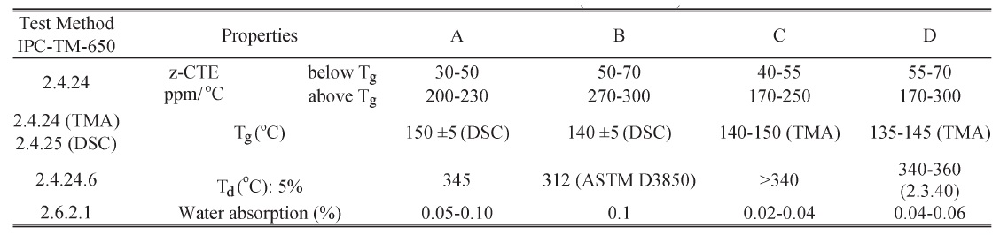
In Ma et al.'s study [93], four PCB materials—two halogen-free (A and C) and two halogenated (B and D)—were tested. These laminates were acquired from two manufacturers (A and B from manufacturer I, and C and D from manufacturer II). The laminate properties are shown in the following table according to their datasheets.
Test Material Properties (Datasheet)
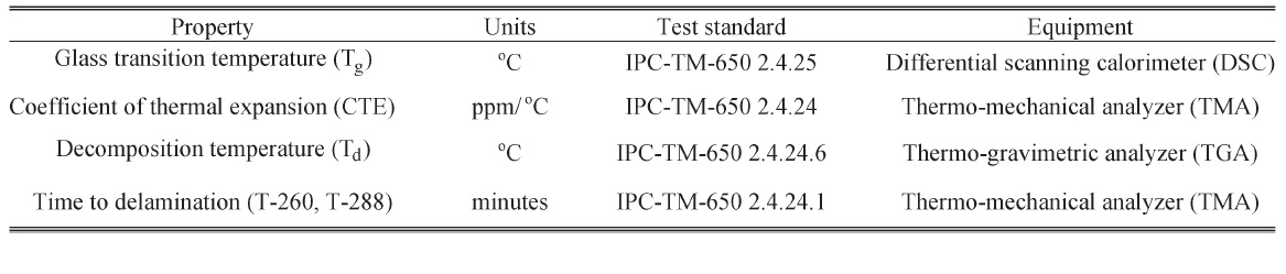
The test methods and equipment used for measuring the properties are listed in the following table. The measurement procedures for each of the properties are discussed in the following manuscripts.
Measurement Methods
1) CTE: The CTE of a laminate system is the fractional change of linear dimensions with temperature. z-CTE is dominated by the resin system, whereas in-plane CTE is dominated by the glass fabric. z-CTE influences failure mechanisms, such as barrel cracking and delamination, and in-plane (warp/fill) CTE affects shear failures of solder joints.
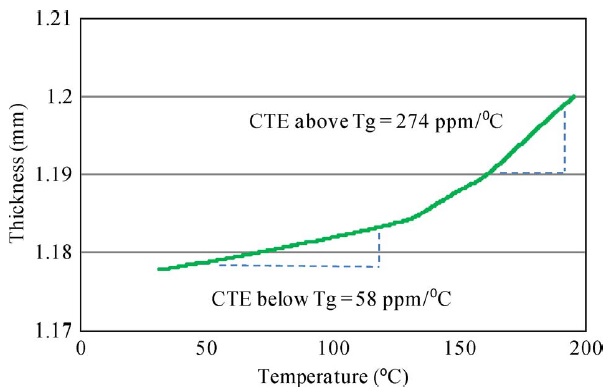
Three samples of each material, each approximately 6.35 mm × 6.35 mm in size, were tested in this study. The samples were polished to ensure parallel edges, and the copper cladding was etched off using sodium per sulfate solution. The CTE of laminate materials along the z-CTE direction was measured using a Perkin–Elmer thermomechanical analyzer (TMA) (Pyris TMA 7). The TMAheated the sample from 30 °C to 200 °C at a 10 °C/min ramp rate. The TMA measured z-CTE by monitoring the sample’s change in thickness. The laminate had one z-CTE below its Tg and another above its Tg, each of which were measured from the TMA results. A typical z-CTE measurement plot is shown in the following figure.
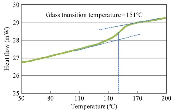
2) Glass-Transition Temperature (Tg): The glass-transition temperature (Tg) of a resin system is the temperature at which a material transforms from a rigid and glasslike state to a rubbery and compliant state due to the reversible breakage of Van der Waals bonds between the polymer molecular chains. Certain properties, such as thermal expansion, Young’s modulus, heat capacity, and dielectric constant, undergo a change at around Tg. Therefore, it is very important to determine the glasstransition temperature under ambient and moisture conditions in order to define the temperature range in which these systems can be used without decreasing their properties at the service temperature.
Three samples from each material type weighing 15–30 mg each were tested. The edges were smoothed and burrs were removed by sanding, and the copper cladding was etched off using sodium per sulfate solution. Tg was measured using a Perkin–Elmer differential scanning calorimeter (DSC) (Pyris 1 DSC). The specimens were subjected to a temperature scan of 30 °C to 200 °C at a rate of 20 °C/min. At Tg, the heat capacity of a material changes, and this is captured by a step transition in the DSC measurement curve. Tg is identified as the midpoint of the step transition (across which the heat capacity of the material changes) in the DSC measurement plot (the following figure).
Glass-transition-temperature Measurement Plot
3) Decomposition Temperature (Td): Decomposition temperature (Td) is the temperature at which a resin system undergoes irreversible physical and chemical degradation with thermal destruction of the cross links, resulting in weight loss of the material. Two samples from each material type weighing 10–20 mg each were tested. The edges were smoothed and burrs were removed by sanding, and the copper cladding was etched off. The Td was measured using a thermogravimetric analyzer (TGA) (Shimadzu TGA 50). The specimens were subjected to a temperature scan of 25 °C to 550 °C at a rate of 10 °C/min. The change in weight of the sample was obtained as a function of temperature, and Td was recorded at 2% and 5% weight loss compared with the sample weight at 50 °C.
4) Time to Delamination (T-260, T-288): Time to delamination is the time it takes for a laminate material to delaminate (defined as the separation between layers of prepregs and copper clad cores in a multilayered structure) when exposed to a constant temperature. A temperature of 260 °C (T-260) is used in the industry as a metric for assessing the leadfree process compatibility of laminates. The T-288 delamination time provides a more appropriate level of performance given the process temperature required for lead-free soldering. Both parameters were tested in this study. Four samples, each 6.35 mm × 6.35 mm in size, were tested using a TMA (Pyris TMA 7). The samples were subjected to a temperature scan of 25 °C to 260 °C or 288 °C at a ramp rate of 10 °C/min and then held at 260 °C or 288 °C until an irreversible change in thickness of the sample was observed or 30 min elapsed, whichever came first [113]. Time to delamination was determined as the time between the onset of isotherm (260 °C or 288 °C) and the onset of delamination.
I - Moisture Absorption and Desorption
The moisture concentration in a laminate increases with exposure time and approaches equilibrium after several days when exposed to a humid environment. The time to reach equilibrium depends on the thickness of the laminate and the ambient temperature. The laminate samples were assumed to be relatively thin. Thus, diffusion from the laminates’ edges was negligible. Moisture diffusion in laminates follows a 1-D Fickian equation. For Fickian diffusion in a laminate with thickness exposed on both sides to the same environment, the moisture content Mt at time t is given by the following expression:

where M∞ is the equilibrium moisture content and D is the diffusion coefficient, or diffusivity, given in square of the length per unit time [96]. Moisture diffusion will only occur through the epoxy, as the reinforcement glass does not readily absorb moisture. Epoxies can also inherently absorb different moisture contents; also, the varying glass/resin ratios between different PCB constructions will result in varying moisture concentrations and maximum moisture-uptake values. As a result, the moisture absorption characteristics of PCB materials will vary by epoxy type, construction, and epoxy/fiber content [114].
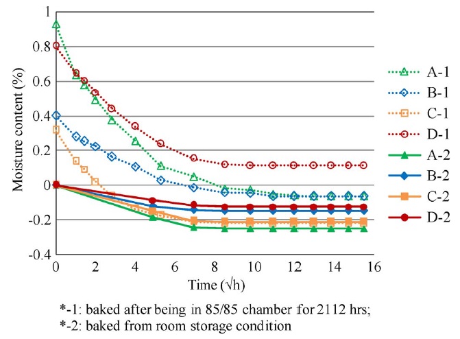
The water molecules absorbed into the epoxy can be classified as either bound water or free water [115], [116]. Bound water is trapped at polar sites and is usually bonded to hydroxyl groups in the epoxy network. Free water is clustered in the free volume or voids inside the epoxy. The free volume of the polymeric resin is defined as the volume of the resin without the volume of the polymer chains or the volume due to thermal vibrations of the polymer chains. The bound water that was bonded to hydroxyl groups in the epoxy network was not released in the baking process. As a result, the moisturecontent values of coupons subject to 85 °C and 85% RH were higher than those of the coupons in room-storage conditions after the baking process, as shown in the following figure:
Rate of moisture desorption of laminates at 105 °C.
II - Moisture Absorption and Desorption
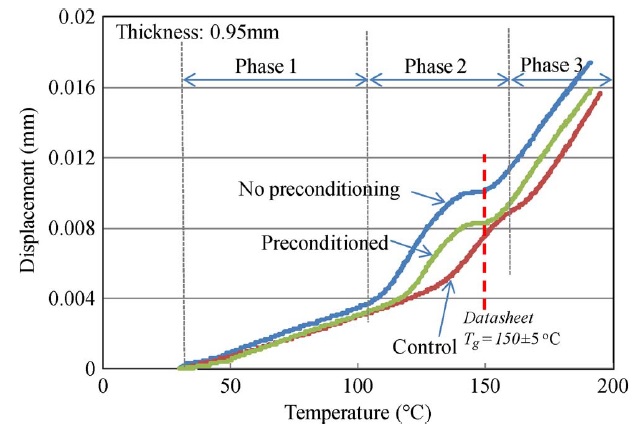
The z-CTE values (below Tg and above Tg) of the four PCB laminates with different moisture contents are plotted and shown in Fig. A. The datasheet regions are also illustrated. Fig. B displays the CTE curves of sample A with different moisture conditions. After exposing sample A to 85 °C and 85% RH for 24 h, one part was preconditioned per IPC-TM-650 2.4.24 test method and then the CTE was measured. The other part was tested without preconditioning. The two results compared with a control set are plotted and shown in Fig. B. Fig. C shows the CTE curves of the four samples that absorbed moisture at 85 °C and 85% RH for various lengths of time and were then preconditioned per IPC-TM-650 2.4.24 test method before measurement.
There was no obvious trend in the z-CTE values calculated from the data below or above the glass-transition region, as shown in Fig. A. However, there was appreciable deviation on the z-CTE curves around the glass-transition region, as shown in Figs. B and C. Preconditioning per IPC test methods can reduce the effect of moisture on z-axis expansion. However, the swelling in the glass-transition region increased with the increase of moisture content, particularly in halogen-free material A, which absorbed more moisture than the other materials in the moisture-absorption experiments.
It can be inferred from the CTE curves in Fig. B that there were three phases, each showing different thermal expansion rates. In phase 1, z-axis expansion was dominated by the resin, and hence, the CTE values below Tg were close to that of epoxy resin (∼60 ppm/°C). In phase 3, the PCB material expanded because an increase in temperature led to greater thermal vibration of the atoms in the material, and hence, there was an increase in the average separation distance of adjacent atoms. Therefore, the PCB material had a large expansion rate and became more viscous above Tg. In phase 2, there were two factors that caused appreciable deviation in the z-CTE values. First, moisture caused swelling in the PCB laminate above 100 °C and increased in the z-axis expansion below the original Tg point. Second, water acted as a plasticizer in the epoxy system, increasing the viscosity of the epoxy resin and resulting in the reduction of Tg. Hence, the expansion rate was large below the original Tg point. As a result, the total z-axis expansion of the laminate increased as the moisture content in the laminate increased.
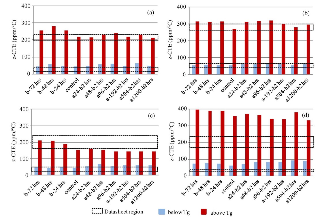
Figure A. z-CTE values of samples with various moisture contents and datasheet regions.
Figure B. CTE curves of sample A after exposure to 85 °C and 85% RH for 24 h. One part was preconditioned by IPC-TM-650 2.4.24 method before measurement compared with no preconditioning part and a control set.
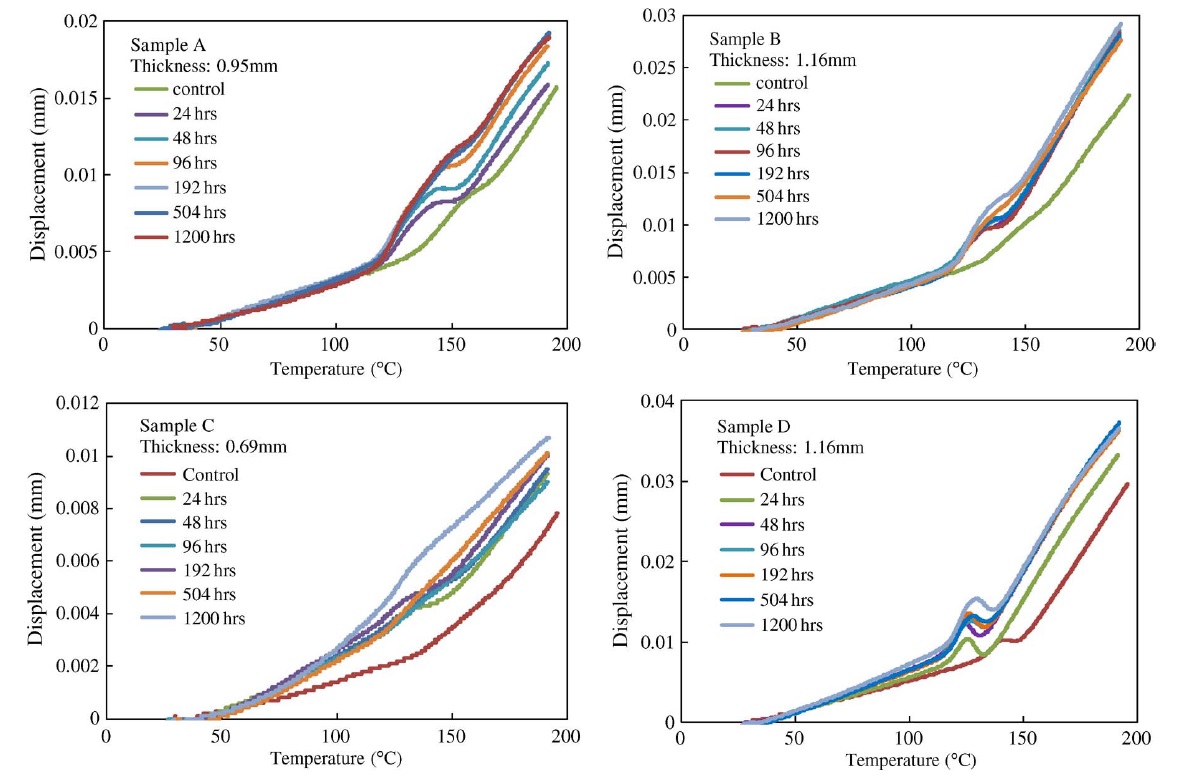
Figure C. CTE curves of the four samples after exposure to 85 °C and 85% RH for various times and later preconditioned per IPC-TM-650 2.4.24 test method before measurement.
III - Effect of Moisture on Tg
Previous work has found that the absorbed water in epoxy materials leads to a decrease in the glass-transition temperature due to the plasticizing effect of water [117]–[120]. DSC results from our experiments proved that the Tg of the epoxy samples did indeed decrease with a moisture increase in the early stages (until around 192 h, except for sample D), as shown in Fig. D. However, Tg increased in the later stages (post-192 h except for sample D) after exposure for a long time to 85 °C and 85% RH. In order to verify that the Tg results obtained from this experiment were also influenced by temperature exposure, Tg tests were repeated on specimens A and B, which were immersed in boiling water. Boiling water was used to accelerate the sample moisture-absorption rate. The results are shown in Fig. E.
The same trends were found in samples A and B when they were immersed in boiling water. The results indicate that the Tg of a water-saturated epoxy depends strongly on exposure time and temperature. At the time when the hygrothermally exposed materials almost reach saturation, the depression of Tg is greatest. However, Tg begins to gradually recover after saturation. A higher immersion temperature and longer immersion time induces a greater degree of recovery of Tg.
A decrease in the Tg of an epoxy system is usually associated with entrapped plasticizers. Water typically acts as a plasticizer in epoxy systems, resulting in the reduction of Tg. An increase in Tg is associated with an increase in cross-linking density. Heat facilitates the chemical reactions that result in the cross linking of polymers, thus increasing Tg. According to the Tg results from both the 85 °C and 85% RH conditions and boiling water, we can see that during the early stages, the test samples absorbed more moisture, Tg decreased rapidly, and moisture dominated the trends. In the later stages, the samples were nearly saturated, Tg increased with time under thermal conditions, and temperature dominated the trends. This kind of behavior can also be explained by the findings of Zhou and Lucas [121]. They have claimed that absorbed water molecules forming double hydrogen bonds would cause an increase in Tg. According to their findings, water molecules bind with epoxy resins through hydrogen bonding. Two types of bound water were found in epoxy resins. The binding types are classified as Type I or Type II bonding, depending on differences in the bond complex and activation energy. These two types of bound water have quite different influences on Tg variation. Type I bound water disrupts the initial interchain Van derWaals force and hydrogen bonds, resulting in increased chain-segment mobility and acting as a plasticizer, thus decreasing Tg. In contrast, Type II bound water contributes to an increase in Tg in water-saturated epoxy resin by forming a secondary crosslink network. Experimentally determined Tg values represent the combined effect of the two mechanisms.
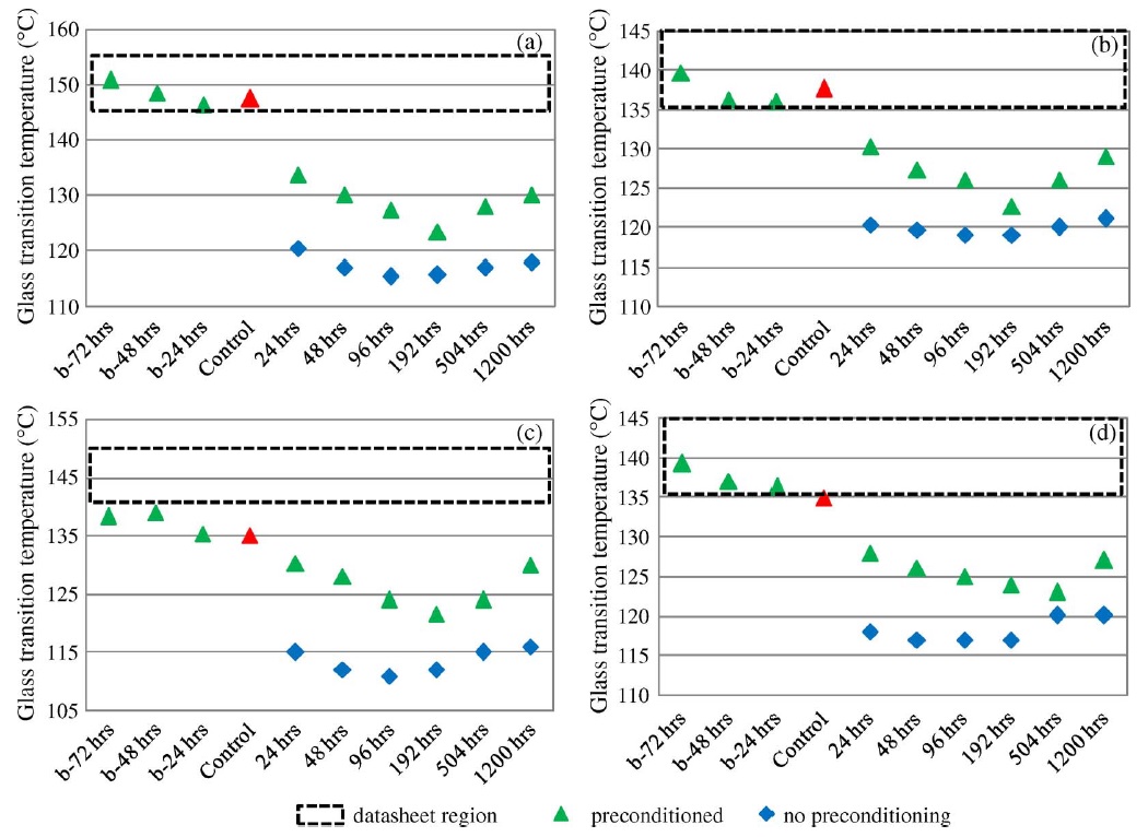
Figure D. Tg results of the four samples after exposure to 85 °C and 85% RH for different durations.
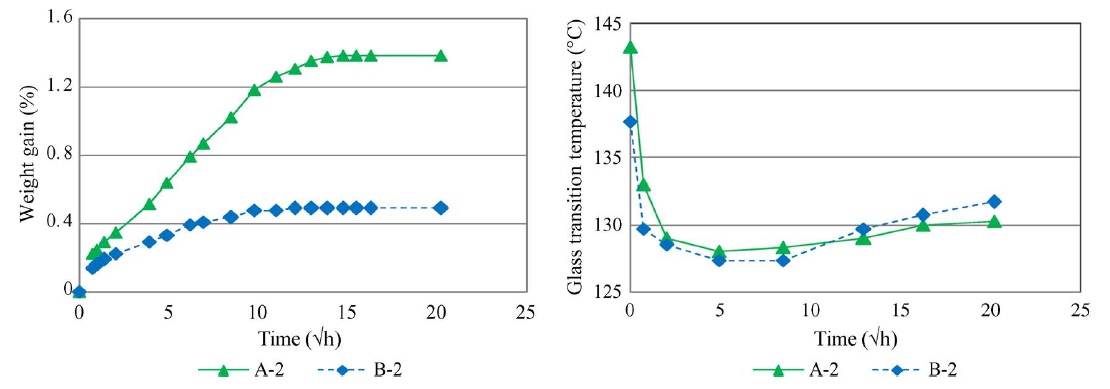
Figure E. Moisture absorption and Tg results of samples A and B in boiling water.
IV - Effect of Moisture on Td
Decomposition temperature measurement was conducted by exposing the specimens to a temperature scan of 25 °C to 550 °C under a flow of nitrogen at a heating rate of 10 °C/min. The decomposition temperature measurement results for the four materials corresponding to 2% and 5% weight loss are plotted and shown in Fig. F. After preconditioning according to IPC-TM-650 2.4.24.6, the Td for the specimen that was saturated in boiling water did not show noticeable variation compared with the control set. In other words, moisture had no obvious effect on Td after preconditioning per IPC standard for all of the materials in this study. Further, typical TGA curves for the four test materials are plotted and shown in Fig. G. The halogenated materials (B and D) started to decompose at 370 °C and 320 °C, respectively, and subsequently experienced a rapid degradation. Materials B and D underwent degradation from 2% to 5% within a narrow temperature range, which was not the case with halogen-free materials (A and C). The halogen-free materials (A and C) experienced a slope degradation, which indicated that the halogen-free materials had better thermal stability than the halogenated materials. The possible reason is that the halogen-free and halogenated materials have different epoxy-resin systems as they use different flame retardants. The mechanism is not yet clear.
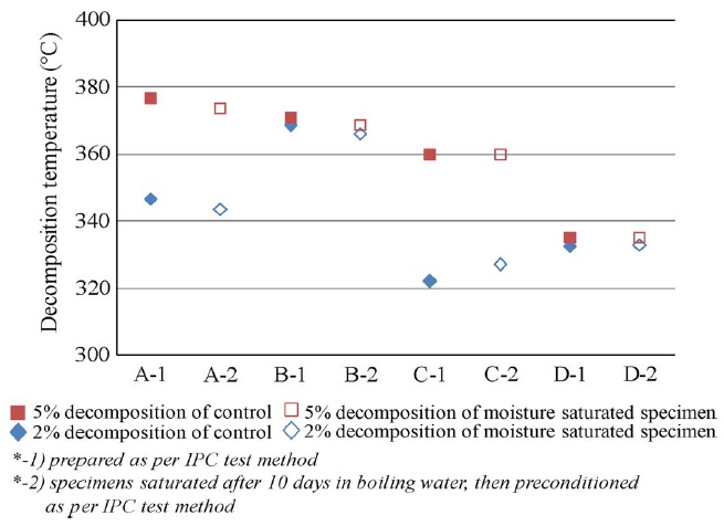
Figure F. Td results of four samples after being saturated in boiling water compared with the control set.
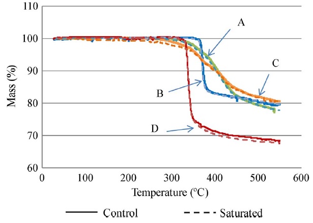
Figure G. Typical TGA curves for the four laminates.
V - Effect of Moisture on Time to Delamination
Two sets of samples were prepared in this test. One set was prepared and tested per IPC-TM-650 2.4.24 as a control. The other set was immersed in boiling water for ten days. The weight of each laminate was measured before and after immersion with an analytical balance. The laminate thickness was measured with a digital vernier caliper with a 0.01-mm least count. This test ramped the sample from 25 °C to 260 °C or 288 °C at 10 °C/min and held the sample at 260 °C or 288 °C until an irreversible change in thickness of the sample was observed or 30 min elapsed, whichever occurred first. The results are shown in the following table.
The time to delamination is a measure of the ability of a dielectric bond line to absorb stresses. As we can see, the time to delamination decreased obviously when materials A and D were immersed in boiling water and absorbed around 1% moisture. The T-260 and T-288 of material B decreased slightly after absorbing 0.5% moisture. Material C did not show any delamination within 30 min in the control set or in the moisture absorption set. Degradation in the time-to-delamination results showed that moisture absorption had affected the bond line.
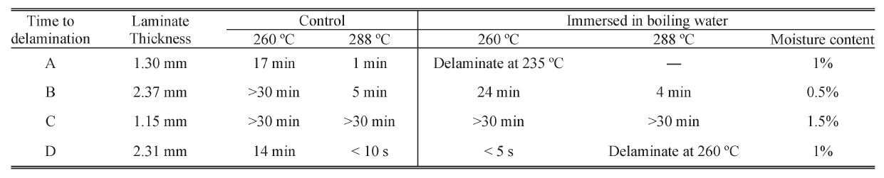
Time to delamination results for four samples after absorbing moisture in boiling water compared with the control set.
-
Color Printable Periodic Table, SCIENCE NOTES. http://sciencenotes.org/printable-periodic-table/
-
European Flame Retardants Association, “Why use flame retardants”, European Flame Retardants Association, 2005.
-
S. O’Connell, A. Whitley, J. Burkitt, S. Ching, A. Fong, T. Brady, and S. Tasa, “Environmental assessment of halogen-free printed circuit boards”, DfE Phase II, HDP User Group International, Inc., Scottsdale, AZ, pp. 1-17, 2004.
-
IPC Association Connecting Electronics Industries, “IPC white paper on halogen-free materials used for printed circuit boards and assemblies”, IPC-WP/TR-584, 2003. available at: www.ipc.org/TOC/IPC-WP-TR-584.pdf
-
IEC 61249-2-21:2003, “Materials for printed boards and other interconnecting structures - Part 2-21: Reinforced base materials, clad and unclad - Non-halogenated epoxide woven E-glass reinforced laminated sheets of defined flammability (vertical burning test), copper-clad,” International Electrotechnical Commission, 2003.
-
JPCA-ES-01-1999 “Test Method for Halogen-Free Materials,” Japan Printed Circuit Association, 1999.
-
J. Davignon, “iNEMI HFR-Free PCB Materials Team Project: An Investigation to Identify Technology Limitations Involved in Transitioning to HFR-Free PCB Materials,” 2012.
-
“UL94 Flammability Standard,” Underwriters Laboratories, 2017. http://www.ulttc.com/en/solutions/test-methods/combustion-fire/flammabil...
-
J. Davignon and R. Pfahl, “Industry transition to halogen-free platforms,” IDF2009 Intel developer forum, 2009.
-
P. Guerra, M. Alaee, E. Eljarrat, and D. Barceló, “Introduction to brominated flame retardants: Commercially products, applications, and physicochemical properties,” The Handbook of Environmental Chemistry, Springer, Vol. 16, pp. 1–18, 2011.
-
R. E. Kirk, D. F. Othmer, “Kirk-Othmer encyclopedia of chemical technology,” Wiley, New York, 2007.
-
M. Alaee, P. Arias, A. Sjödin, Å. Bergman, “An overview of commercially used brominated flame retardants, their applications, their use patterns in different countries/regions and possible modes of release,” Environment International, Vol. 29, No. 6, pp. 683–689, 2003.
-
P. O. Darnerud, “Toxic effects of brominated flame retardants in man and in wildlife,” Environment International, Vol. 29, No. 6, pp. 841-853, 2003.
-
A. Covaci, S. Voorspoels, L. Ramos, H. Neels, and R. Blust, “Recent developments in the analysis of brominated flame retardants and brominated natural compounds,” Journal of Chromatography A, Vol. 1153, Nos. 1–2, pp. 145–171, 2007.
-
R. J. Law, D. Herzke, S. Harrad, S. Morris, P. Bersuder, and C. R. Allchin, “Levels and trends of HBCD and BDEs in the European and Asian environments, with some information for other BFRs,” Chemosphere, Vol. 73, No. 2, pp. 223–241, 2008.
-
A. Covaci, S. Voorspoels, M. Abou-Elwafa, Abdallah, T. Geens, S. Harrad, and R. J. Law, “Analytical and environmental aspects of the flame retardant tetrabromobisphenol-A and its derivatives,” Journal of Chromatography A, Vol. 1216, No. 3, pp. 346–363, 2009.
-
B. Schartel, A. I. Balabanovich, U. Braun, U. Knoll, J. Artner, M. Ciesielski, M. Döring, R. Perez, J. K. W. Sandler, V. Altstädt, T. Hoffmann, and D. Pospiech, “Pyrolysis of epoxy resins and fire behavior of epoxy resin composites flame‐retarded with 9,10‐dihydro‐9‐oxa‐10‐phosphaphenanthrene‐10‐oxide additives,” Journal of Applied Polymer Science, Vol. 104, No. 4, pp. 2260–2269, 2007.
-
X. Wang, Y. Hu, L. Song, W. Y. Xing, H. D. Lu, P. Lv, and G. Jie, “Flame retardancy and thermal degradation mechanism of epoxy resin composites based on a DOPO substituted organophosphorus oligomer,” Polymer, Vol. 51, No. 11, pp. 2435–2445, 2010.
-
H. Liu, S. Zheng, and K. Nie, “Morphology and thermomechanical properties of organic-inorganic hybrid composites involving epoxy resin and an incompletely condensed polyhedral oligomeric silsesquioxane,” Macromolecules, Vol. 38, No. 12, pp. 5088–5097, 2005.
-
L. Qian, Y. Qiu, N. Sun, M. Xu, G. Xu, F. Xin, and Y. Chen, “Pyrolysis route of a novel flame retardant constructed by phosphaphenanthrene and triazine-trione groups and its flame-retardant effect on epoxy resin,” Polymer Degradation and Stability, Vol. 107, pp. 98–105, 2014.
-
W. Xu, A. Wirasaputra, S. Liu, Y. Yuan, and J. Zhao, “Highly effective flame retarded epoxy resin cured by DOPO-based co-curing agent,” Polymer Degradation and Stability, Vol. 122, pp. 44–51, 2015.
-
J. Brus, M. Urbanova, and A. Strachota, “Epoxy networks reinforced with polyhedral oligomeric silsesquioxane: structure and segmental dynamics as studied by solid-state NMR,” Macromolecules, Vol. 41, No. 2, pp. 372–386, 2008.
-
R. Liu and X. Wang, “Synthesis, characterization, thermal properties and flame retardancy of a novel nonflammable phosphazene-based epoxy resin,” Polymer Degradation and Stability, Vol. 94, No. 4, pp. 617–624, 2009.
-
L. Becker, D. Lenoir, G. Matuschek, and A. Kettrup “Thermal degradation of halogen-free flame retardant epoxides and polycarbonate in air,” Journal of Analytical and Applied Pyrolysis, Vol. 60, No. 1, pp. 55–67, 2001.
-
M. G. Pecht, L. T. Nguyen, and E. B. Hakim, “Plastic Encapsulated Microelectronics,” New York: John Wiley, 1994.
-
N. Kinjo, M. Ogata, K. Nish, and A. Kaneda, “Epoxy molding compounds as encapsulation materials for microelectronic devices,” In: Speciality Polymers/Polymer Physics. Advances in Polymer Science, Vol. 88, pp. 1−48, Springer, Berlin, Heidelberg, 1989.
-
M. Goosey, “Plastics for electronics,” Elsevier Applied Science, London & New York, 1985.
-
E. W. Flick, “Epoxy resins, curing agents, compounds, and modifiers: An industrial guide (2nd edition),” Noyes Publications, Park Ridge, New Jersey, USA, 1993.
-
N. Nimpuno, A. McPherson, and T. Sadique, “Greening consumer electronics − Moving away from bromine and chlorine.” September 2009. Accessed May 09, 2018. Available online: http://www.cleanproduction.org/static/ee_images/uploads/resources/NanYa-...
-
“FR-4 PCB Materials,” Sunstone Circuits, 2016. Accessed May 09, 2018. Available online: http://www.sunstone.com/pcb-capabilities/pcb-manufacturing-capabilities/...
-
L. S. Birnbaum and D. F. Staskal, “Brominated flame retardants: cause for concern?” Environmental Health Perspectives, Vol. 112, No. 1, pp. 9-17, 2004.
-
T. Malkoske, Y. Tang, W. Xu, S.Yu, and H. Wang, “A review of the environmental distribution, fate, and control of tetrabromobisphenol A released from sources,” Science of the Total Environment, Vol. 569-570, pp. 1608-1617, 2016.
-
B. Ghosh, M. K. Ghosh, P. Parhi, P. S. Mukherjee, and B. K. Mishra, “Waste printed circuit boards recycling: an extensive assessment of current status,” Journal of Cleaner Production, Vol. 94, pp. 5–19, 2015.
-
“iNEMI timeline for HFR-free electronics and PVC-free cabling for notebook and desktop products,” International Electronics Manufacturer Initiative, 2010. Available online: http://thor.inemi.org/webdownload/projects/ELSC/HFR-Free_PVC-Free_Timeli...
-
A. Soler, J. A. Conesa, and N. Ortuño, “Emissions of brominated compounds and polycyclic aromatic hydrocarbons during pyrolysis of E-waste debrominated in subcritical water,” Chemosphere, Vol. 186, pp. 167-176, 2017.
-
US EPA, In: US EPA (Ed.), Method 5050, “Bomb preparation method for solid waste,” United States Environmental Protection Agency, Office of Solid Waste, Washington, D.C. SW-846, 1994.
-
US EPA, In: US EPA (Ed.), Method 9056A, “Determination of inorganic anions by ion chromatography,” United States Environmental Protection Agency, Office of Solid Waste, Washington, D.C. SW-846, 2000.
-
Ministry of Environment and Energy, Danish Environmental Protection Agency, Action plan for brominated flame retardants. March 2001.
-
M. Wensing, "Measurement of VOC and SVOC emissions from computer monitors with a 1 m3 emission test chamber," Proceedings of joint international congress and exhibition, electronics goes green 2004+. Berlin, Germany, Stuttgart: Fraunhofer IRB Verlag, pp. 759–764, 2004.
-
Emission and evaluation of chemical substances from selected electrical and electronic products. Survey no. 32—2003, Danish EPA; June 2003. Available online: http://www.mst.dk/chemi/01082601.htm.
-
K. Vorkamp, "Occurrence of "new" contaminants in marine biota in Greenland and the Faroe Islands," Department of Environmental Chemistry and Microbiology, National Environmental Research Institute, Danish Ministry of the Environment, 2005. Available online: http://projects.amap.no/project/occurence-of-new-contaminants-in-marine-....
-
K. Vorkamp, "Danish National Monitoring Programme (NOVANA)—point sources," Department of Environmental Chemistry and Microbiology, National Environmental Research Institute, Danish Ministry of the Environment, Available online: http://www2.dmu.dk/1_Om_DMU/2_akt-proj/abstractmvNav.asp?Anr=21-5575.
-
Alicja Mortensen, Kit Granby, Folmer D. Eriksen, Tommy Licht Cederberg, Søren Friis-Wandall, YvonneSimonsen, Birgitte Broesbøl-Jensen, and Rikke Bonnichsen, "Levels and risk assessment of chemical contaminants inbyproducts for animal feed in Denmark," Journal of Environmental Science and Health, Part B: Pesticides, Food Contaminants, and Agricultural Wastes, Vol. 49, No.11, pp. 797-810, 2014.
-
de Wit CA, "An overview of brominated flame retardants in the environment," Chemosphere, Vol. 46, No. 5, pp. 583–624, 2002.
-
Government Concentrates, "EU restricts brominated flame retardants," Chemical & Engineering News, Vol. 79, No. 38, p. 33, 2001.
-
C. Schubert, "Burned by flame retardants," Science News, Vol. 160, No. 15, p. 238, 2001.
-
Government Concentrates, "EU restricts brominated flame retardants," Chemical & Engineering News, Vol. 79, No. 38, p. 33, 2001.
-
C. Schubert, "Burned by flame retardants," Science News, Vol. 160, No. 15, p. 238, 2001.
-
S. Darnerud, "Effects of PBDEs and PCBs on thyroxin and TSH blood levels in rats and mice," Organohalogen Compd, Vol. 29, pp. 316–319, 1996.
-
J. R. Fowles, A. Fairbrother, L. Baecher-Steppan, N. I. Kerkvliet, "Immunologic and endocrine effects on the flame retardant penta-BDE (DE-71) in C57BL/6J mice," Toxicology, Vol. 86, pp. 49–61, 1994.
-
I. Meerts, G. Marsh, I. van Leeuwen-Bol, E. Luijks, E. Jakobsson, Å. Bergman, A. Brouwer, "Interaction of polybrominated diphenyl ether metabolites (PBDE-OH) with human transthyretin in vitro" 18th Symposium on Halogenated Environmental Organic Pollutants, Organohal. Comp. Vol. 37, pp. 309–312, 1998.
-
M. J. L. Guardia, R. C. Hale, and E. Harvey, “Detailed polybrominated diphenyl ether (PBDE) congener composition of the widely used Penta-, Octa-, and Deca-PBDE technical flame-retardant mixtures,” Environmental Science & Technology, Vol. 40, No. 20, pp. 6247-6254 , 2006.
-
“RoHS Guide.” RoHS Compliance Guide: Regulations, 6 Substances, Exemptions, WEEE. Accessed July 22, 2016. Available online: http://www.rohsguide.com/
-
“Flame retardants & PVC in electronics.” – Electronics TakeBack Coalition. Accessed July 22, 2016. Available online: http://www.electronicstakeback.com/toxics-in-electronics/flame-retardant...
-
“RoHS compliance FAQ.” RoHS Compliance Definition. Accessed July 27, 2016. Available online: http://www.rohscompliancedefinition.com/rohs-compliance-faq.html
-
API Technologies Corp. “Why should I care about RoHS and lead-free initiatives?” Accessed July 27, 2016. Available online: http://apitech.com/product-classes/why-should-i-care-about-rohs-and-lead...
-
R. Wright, “Role of fillers/reinforcements in thermosetting molding compounds,” Regional Technical Conference––Society of Plastics Engineers, pp. 83–92, 1992.
-
M. M. Khan and H. Fatemi, “Gold–aluminum bond failure induced by halogenated additives in epoxy molding compounds,” Proceedings IEEE International Reliability Physics Symposium, pp. 420–428, 1986.
-
L. T. Nguyen, R. H. Y. Lo, A. S. Chen, and J. G. Belani, “Molding compound trends in a denser packaging world: qualification tests and reliability concerns,” IEEE Transactions on Reliability, Vol. 42, No. 4, pp. 518–35, 1993.
-
P. McCluskey, R. Munamarty, and M. G. Pecht, “Popcorning in PBGA packages during IR reflow soldering,” Microelectronics International, pp. 20–23, 1997.
-
A. Hale, M. Garcia, C. W. Macosko, and L. T. Manzione, “Spiral flow modelling of a filled epoxy-novolac molding compound,” Proceedings SPE ANTEC, pp. 796–799, 1989.
-
L. T. Nguyen, S. A. Gee, M. R. Johnson, H. E. Grimm, H. Berardi, and R. L. Walberg, “Effects of die coatings, mold compounds, and test conditions on temperature cycling failures,” IEEE Transactions on Components and Packaging Technologies––Part A, Vol. 18, No. 1, pp. 15–22, 1995.
-
E. A. Sullivan, “Thermal degradation of epoxy novolacphenol formaldehyde novolac resin systems,” Journal of Applied Polymer Science, Vol. 42, No. 7, pp. 1815–1828, 1991.
-
D. J. Belton, E. A. Sullivan, and M. J. Molter, “Moisture transport phenomena in epoxies for microelectronics applications,” in: Polymeric Materials for Electronics Packaging and Interconnection, Washington, DC: American Chemical Society, pp. 286–320, 1989.
-
J. S. Wang, Y. Liu, H. B. Zhao, J. Liu, D. Y. Wang, Y. P. Song, and Y. Z. Wang, “Metal compound-enhanced flame retardancy of intumescent epoxy resins containing ammonium polyphosphate,” Polymer Degradation and Stability, Vol. 94, No. 4, pp. 625–631, 2009.
-
W. S. Chow and S. S. Neoh “Dynamic mechanical, thermal, and morphological properties of silane-treated montmorillonite reinforced polycarbonate nanocomposites,” Journal of Applied Polymer Science, Vol. 114, No. 6, pp. 3967–3975, 2009.
-
World Flame Retardants, Industry Study 3258, Thr Freedonia Group, February 2015. https://www.freedoniagroup.com/industry-study/world-flame-retardants-325...
-
Global Flame Retardants Market 6th Edition, Industry Study 3499, Thr Freedonia Group, February 2017. https://www.freedoniagroup.com/industry-study/global-flame-retardants-ma...
-
C. J. Orme, J. R. Klaehn, M. K. Harrup, R. P. Lash, and F. F. Stewart, “Characterization of 2-(2-methoxyethoxy)ethanol-substituted phosphazene polymers using pervaporation, solubility parameters, and sorption studies,” Journal of Applied Polymer Science, Vol. 97, pp. 939–945, 2005.
-
N. Lejeune, I. Dez, P. A. Jaffres, J. F. Lohier, P. J. Madec, and J. Sopkova-de Oliveira Santos, “Synthesis, crystal structure and thermal properties of phosphorylated cyclotriphosphazenes,” European Journal of Inorganic Chemistry, Vol. 1, pp. 138–143, 2008.
-
U. Braun, B. Schartel, M. A. Fichera, and C. Jager, “Flame retardancy mechanisms of aluminium phosphinate in combination with melamine polyphosphate and zinc borate in glass-fibre reinforced polyamide 6.6,” Polymer Degradation and Stability, Vol. 92, pp. 1528–1545, 2007.
-
K. N. Subramanian, “Lead-free Solders: Materials Reliability for Electronics,” John Wiley & Sons, Ltd, 2012. Available online: http://onlinelibrary.wiley.com/book/10.1002/9781119966203
-
D. Shangguan, “Lead-Free Solder Interconnect Reliability,” ASM International, 2005.
-
H. D. Solomon, “Fatigue of 60/40 solder,” IEEE Trans. Compon. Hybrids Manufact. Technol., Vol. CHMT-9, pp. 423–432, 1986.
-
J-P. Clech, J. C. Manock, D. M. Noctor, F. E. Bader, and J. A. Augis, “A comprehensive surface mount reliability model: background, validation and applications,” In Proc. 40th Electronic Components and Technology conference, pp. 62–70, 1993.
-
“What does halogen-free mean?” April 4, 2014. Accessed July 18, 2016. Available online: http://barcode-labels.com/what-does-halogen-free-mean/
-
W. Zhang, X. He, T. Song, W. Jiao, and R. Yang, “The influence of the phosphorus-based flame retardant on the flame retardancy of the epoxy resins,” Polymer Degradation and Stability, Vol. 109, pp. 209–217, 2014.
-
H. F. Zhong, P. Wei, P. K. Jiang, and G. L. Wang, “Thermal degradation behaviors and flame retardancy of PC/ABS with novel silicon-containing flame retardant,” Fire Materials, Vol. 31, pp. 411–423, 2007.
-
S. Y. Lu and I. Hamerton, “Recent developments in the chemistry of halogen-free flame retardant polymers,” Progress in Polymer Science, Vol. 27, pp. 1661–712, 2002.
-
B. Schartel, U. Braun, A. I. Balabanovich, J. Artner, M. Ciesielski, M. Döring, R. M. Perez, J. K. W. Sandler, and V. Altstädt, “Pyrolysis and fire behavior of epoxy systems containing a novel 9,10-dihydro-9-oxa-10-phosphaphenanthrene-10-oxide-(DOPO)-based diamino hardener,” European Polymer Journal, Vol. 44, pp. 704–715, 2008.
-
J. Artner, M. Ciesielski, O. Walter, M. Döring, R. M. Perez, J. K. W. Sandler, V. Altstädt, and B. Schartel, “A novel DOPO-based diamine as hardener and flame retardant for epoxy resin systems,” Macromolecular Materials and Engineering, Vol. 293, pp. 503–514, 2008.
-
X. Wang, Y. Hu, L. Song, W. Y. Xing, and H. D. Lu, “Thermal degradation behaviors of epoxy resin/POSS hybrids and phosphorus-silicon synergism of flame retardancy,” Journal of Polymer Science Part B: Polymer Physics, Vol. 48, pp. 693–705, 2010.
-
H. T. Lin, C. H. Lin, Y. M. Hu, and W. C. Su, “An approach to develop high-Tg epoxy resins for halogen-free copper clad laminates,” Polymer, Vol. 50, pp. 5685–5692, 2009.
-
W. S. Liu, Z. G. Wang, L. Xiong, and L. N. Zhao, “Phosphorus-containing liquid cycloaliphatic epoxy resins for reworkable environment-friendly electronic packaging materials,” Polymer, Vol. 51, pp. 4776–4783, 2010.
-
C. H. Lin, C. C. Feng, and T. Y. Hwang, “Preparation, thermal properties, morphology, and microstructure of phosphorus-containing epoxy/SiO2 and polyimide/SiO2 nanocomposites,” European Polymer Journal, Vol. 43, pp. 725–742, 2007.
-
X. D. Qian, L. Song, Y. Hu, R. K. K. Yuen, and L. J. Chen, “Combustion and thermal degradation mechanism of a novel intumescent flame retardant for epoxy acrylate containing phosphorus and nitrogen,” Industrial and Engineering Chemistry Research, Vol. 50, pp. 1881–1892, 2011.
-
S. Bourbigot, B. M. Le, S. Duquesne, and M. Rochery, “Recent advances for intumescent polymers,” Macromolecular Materials and Engineering, Vol. 289, pp. 499–511, 2004.
-
B. B. Wang, Q. L. Tai, S. B. Nie, K. Q. Zhou, Q. B. Tang, Y. Hu, and L. Song, “Electron beam irradiation cross linking of halogen-free flame retardant ethylene vinyl acetate (EVA) copolymer by silica gel microencapsulated ammonium polyphosphate and char-forming agent,” Industrial and Engineering Chemistry Research, Vol. 50, pp. 596–605, 2011.
-
X. Li, Y. X. Ou, and Y. S. Shi, “Combustion behavior and thermal degradation properties of epoxy resins with a curing agent containing a caged bicyclic phosphate,” Polymer Degradation and Stability, Vol. 77, pp. 383–390, 2002.
-
X. Wang, Y. Hu, L. Song, W. Y. Xing, H. D. Lu, P. Lv, and G. Jie, “Effect of a triazine ring containing charing agent on fire retardancy and thermal degradation of intumescent flame retardant epoxy resins,” Polymers for Advanced Technologies, Vol. 22, pp. 2480–2487, 2011.
-
P. Hamilton, G. Brist, B. Guy, Jr., and J. Schrader, “Humidity dependent loss in PCB substrates,” in Proc. IPC Printed Circuit Expo, Feb. 2007.
-
S. Tisdale, J. Davignon, S. Hall, M. Leddige, S. Hinaga, and D. Senk, “iNEMI HFR-free leadership project: An investigation to identify technology limitations involved in transitioning to HFR-free PCB materials,” in: 2012 Electronics Goes Green 2012+, pp. 1–8, IEEE, 2012.
-
L. Ma, B. Sood, and M. Pecht, “Effect of Moisture on Thermal Properties of Halogen-Free and Halogenated Printed-Circuit-Board Laminates,” IEEE TRANSACTIONS ON DEVICE AND MATERIALS RELIABILITY, Vol. 11, No. 1, pp. 66-75, 2011.
-
T. L. Welsher, J. P. Mitchell, and D. J. Lando, "CAF in composite printed-circuit substrates: characterization, modeling, and a resistant material," Reliability Physics, 18th Annual Proceeding, pp. 235–237, 1980.
-
B. Rudra, M. Pecht, and D. Jennings, “Assessing time-to-failure due to conductive filament formation in multi-layer organic laminates,” IEEE Trans. Compon., Packag., Manuf. Technol. B, Vol. 17, No. 3, pp. 269–276, Aug. 1994.
-
M. Pecht, H. Ardebili, A. A. Shukla, J. K. Hagge, and D. Jennings, “Moisture ingress into organic laminates,” IEEE Trans. Compon. Packag. Technol., volVol. 22, Nno. 1, pp. 104–110, Mar. 1999.
-
T. Jensen and R. Lasky, “Challenges toward implementing a halogen-free PCB assembly process,” IPC APEX EXPO Conference, Utica NY, 2008. Available online: http://www.circuitinsight.com/pdf/halogen_free_pcb_assembly_ipc.pdf.
-
S. Tisdale, G. B. Long, R. Krabbenhoft, K. Papathomas, and T. Fischer, “iNEMI BFR-free PCB materials evaluation project report,” SMTA International, Orlando, Florida, August 21, 2008.(http://thor.inemi.org/webdownload/newsroom/Presentations/BFR-Free/BFR-Fr...)
-
J. N. Lathi, R. H. Delaney, and J. N. Hines, "The characteristic wear-out process in epoxy glass printed circuits for high density electronic packaging," Reliability Physics, 17th Annual Proceeding, pp. 39–43, 1979.
-
D. J. Lando, J. P. Mitchell, and T. L. Welsher, "Conductive anodic filaments in reinforced polymeric dielectrics: Formation and prevention," Reliability Physics, 17th Annual Proceeding, pp. 51–63, 1979.
-
T. L. Welsher, J. P. Mitchell, and D. J. Lando, "CAF in composite printed-circuit substrates: characterization, modeling, and a resistant material," Reliability Physics, 18th Annual Proceeding, pp. 235–237, 1980.
-
L. J. Turbini, W. R. Bent, and W. J. Ready, "Impact of higher melting lead-free solders on the reliability of printed wiring assemblies," J. Surf. Mount Tech. pp. 10–14, 2000.
-
E. Kelley, "An assessment of the impact of lead-free assembly processes on base material and PCB reliability," Proceedings of IPC APEX Conference pp. S16-2-1 , 2004.
-
K. Sauter, "Electrochemical migration testing results: evaluating PCB design, manufacturing process, and laminate material impacts on CFF resistance," CircuiTree, 2002.
-
B. Sood and M. Pecht, “Conductive filament formation in printed circuit boards: effects of reflow conditions and flame retardants,” J Mater Sci: Mater Electron, Vol. 22, pp. 1602–1615, 2011.
-
IPC, "International technology roadmap for electronic interconnections at IPC APEX Expo, March 31–April 2, Las Vegas, NV, 2009.
-
J. A. Augis, D. G. DeNure, M. J. LuValle, J. P. Mitchell, M. R. Pinnel, and T. L. Welsher, "A humidity threshold for conductive anodic filaments in epoxy glass printed wiring boards," 3rd International SAMPE Electronics Conference, pp. 1023–1030, 1989.
-
B. S. Rudra and M. G. Pecht, "Assessing time-to-failure due to conductive filament formation in multi-layer organic laminates," Packag. Manuf. Tech. Part B, Vol. 17, No. 3, pp. 269–276, 1994.
-
M. Li, K. Gohari, and M. Pecht, "Effect of temperature and humidity cycling on FR-4, bismaleide triazine and cyanate ester printed wiring boards," 7th International SAMPE Electronics Conference—Critical Materials Processing in a Changing World, pp. 446–457, 1994.
-
M. Pecht, A. Haleh, A. Shukla, J. Hagge, and D. Jennings, "Moisture ingress into organic laminates," IEEE Trans. Comp. Packag. Tech, Vol. 22, No. 1, pp. 104–110, 1999.
-
V. William, "Conductive anodic filament resistant resins," Proceedings of the IPC Printed Circuits Expo, 2002.
-
W. J. Ready, L. J. Turbini, S. R. Stock, and B. A. Smith, "Conductive anodic filament enhancement in the presence of a polyglycol-containing flux," IEEE International Reliability Physics Proceedings, pp. 267–273, 1996.
-
The Institute for Interconnecting and Packaging Electronic Circuits, "Time to delamination by TMA," Northbrook, IL, Dec. 1994, IPC-TM-650 2.4.24.1.
-
P. Hamilton, G. Brist, B. Guy, Jr., and J. Schrader, “Humidity dependent loss in PCB substrates,” in Proc. IPC Printed Circuit Expo, Feb. 2007. [Online]. Available: http://www.ipc.org/ContentPage.aspx?
-
pageid=IPC-Honors-Best-Papers-at-IPC-Printed-Circuits-Expo-APEXand-the-Designers-Summit
-
H. Zhao and R. K. Y. Li, “Effect of water absorption on the mechanical and dielectric properties of nano-alumina filled epoxy nanocomposites,” Composites: Part A, Appl. Sci. Manuf., Vol. 39, No. 4, pp. 602–611, Apr. 2008.
-
C. Maggana and P. Pissis, “Water sorption and diffusion studies in an epoxy resin system,” J. Polym. Sci. A, Polym. Chem., Vol. 37, No. 11, pp. 1165–1182, 1999.
-
P. Moy and F. E. Karasz, “Epoxy–water interactions,” Polym. Eng. Sci., Vol. 20, No. 4, pp. 315–319, Mar. 1980.
-
S. Luo, J. Leisen, and C. P. Wong, “Study on mobility of water and polymer chain in epoxy and its influence on adhesion,” J. Appl. Polym. Sci., Vol. 85, No. 1, pp. 1–8, Jul. 2002.
-
E. L. McKague, Jr., J. D. Reynolds, and J. E. Halkias, “Swelling and glass transition relations for epoxy matrix materials in humid environments,” J. Appl. Polym. Sci., Vol. 22, No. 6, pp. 1643–1654, Jun. 1978.
-
E. S. W. Kong and M. J. Adamson, “Physical ageing and its effect on the moisture sorption of amine cured epoxy,” Polym. Commun., Vol. 24, pp. 171–173, 1983.
-
J. M. Zhou and J. P. Lucas, “Hygrothermal effects of epoxy resin part I: The nature of water in epoxy,” Polymer, Vol. 40, No. 20, pp. 5505–5512, Sep. 1999.
For the inquiries about halogen-free electronics, please contact Professor Michael Pecht.