Explanation of the Stress Tests
Stress Test Background
Thermal Shock is one of the conventional stresses, following the Hot and Cold Step Stress sequentially, being used in HALT for defect precipitation for the purpose of design margins improvement. This is also a typical stress that is used to evaluate CTE mismatch issues in electronic systems.
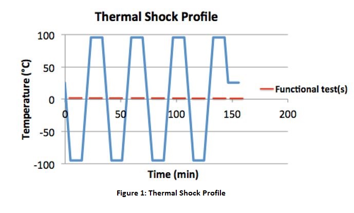
The stress profile shown in Figure 1 at the bottom resembles the test descriptions in IPC 9592A, IEST-RP-PR-003.1, and GMW 3172 for HALT. Therefore, apart from the ability in precipitating defects with the stress, detecting failures with functional tests, relationship between types of failures and discrete stress levels is also addressed in the profile design for proper corrective actions be made for the improvement in design margins.
Stress Profile Description
Typically starts at room temperature, ramp between Tmin and Tmax at a desired ramp rate for specific number of cycles. Maximized functional test coverage should be engaged during testing.
Parameters Determination
Dwell time
Should be determined by stabilization time of the unit. Different thermal stability criteria should be used for different purposes. For placement of functional testing during dwell time, it should also be long enough to cover functional testing duration.
For design improvement purposes (HALT), more stringent thermal stability criteria (entire unit should reach target temperature) is more appropriate so that defects at unexpected locations can be uncovered.
For screening purposes (HASS, ESS), less stringent thermal stability criteria (locations of interest should reach target temperature) may be preferred so that expected defects can be precipitated over a shorter span of time and without life of other parts/ locations being over-consumed by the long stabilization time.
Target stress level in this case, Tmin, Tmax and Ramp Rate
Should be determined based on the purpose of defect precipitation.
For design improvement purposes (HALT), stress levels to be high enough to precipitate defects that can cause failures below the desired stress limits or before the desired lifetime. If used after Cold Step Stress and Hot Step Stress as in conventional HALT, the stress limits determined in these tests are often used for determination of Tmax and Tmin in Thermal Shock. Tmin and Tmaxare set to be within 5 to 10°C of the upper and lower operating limits as suggested by the listed standards. Ramp rates are suggested to be at least 20°C/ min, at least 45 °C/ min, and maximum attainable ramp rate as recommended by IEST-RP-PR-003.1, IPC 9592A, and GMW 8287 respectively, convincingly due to the different scopes of products the standards cover.
For screening purposes (HASS, ESS), target stress levels should be set lower to allow for sufficient remaining lifetime of the population with less critical defects remain in the products. For HASS, it is suggested by the listed standards that the Tmax and Tmin should be 80 -85% of upper and lower operating limits found in HALT in combination with vibration during dwell times.
Number of Cycles
Should be determined based on the purpose of defect precipitation.
For design improvement purposes (HALT), higher number cycles can be appropriate for more defects to be precipitated and corrected for field robustness of the product. There is a big difference regarding this parameter from the listed HALT standards, while at least 3 thermal cycles are suggested by IEST-RP-PR-003.1 and GMW 8287, IPC 9592A suggests at least 30 thermal cycles.
For screening purposes (HASS, ESS), also depend on the stress limits being decided, remaining life of the good population should be taken into account when deciding number of cycles.
Standards with Stress Test Description
For Design Improvement Purpose
- IPC 9592A: Requirements for Power Conversion Devices for the Computer and Telecommunications Industries
- IEST RP PR 003.1: HALT and HASS
- GMW 3172: Highly Accelerated Life Testing (HALT) Highly Accelerated Stress Screening and Auditing
For Testing/ Acceptance Purpose-System Level
- JESD22-A104-E: Temperature Cycling
- JESD22-A106-B: Thermal Shock
For Testing/ Acceptance Purpose-Component Level
- MIL-STD-883-J: Method 1010.8: Test Method Standard for Microcircuits: Temperature Cycling
- MIL-STD-883-J: Method 1011: Test Method Standard for Microcircuits: Thermal Shock Testing
- MIL-STD-202H: Method 107G: Test Method Standard for Electronic and Electrical Component Parts: Thermal Shock
Typical Defects Precipitated by this Stress
|
Defect Location |
Typical Defects |
Failure Mechanism(s) |
|
Solder Joints |
Voids |
• Thermal fatigue which initiates with small defects and propagates to a detectable crack in solder joints |
|
Cracks |
||
|
Insufficient Solder |
||
|
Board Layers |
Board Warpage |
• Interface degradation due to the difference in Coefficient of Thermal Expansion (CTE) |
|
Blistering/ Delamination |
||
|
Metallizations |
Poor Adhesion of Surface Traces |
|
|
Internal Trace Delamination |
||
|
Plated Through Holes (PTHs) |
Poor Hole Fill |
• Thermal fatigue which initiates with small defects and propagates to a detectable crack in PTHs. |
|
Glass Fiber Protrusion |
||
|
Irregular Plating |
||
|
Plating Voids |
||
|
Resin Smear |
• Interface degradation due to the difference in CTE • Thermal fatigue which initiates with small defects and propagates to a detectable crack in PTHs. |
|
|
Microvias |
Voids |
• Thermal fatigue which initiates with small defects and propagates to a detectable crack in microvias. |
|
Cracks |
||
|
Poor Bonding of Pad/ Via Interface |
• Interface degradation due to the difference in CTE |
Top